The engineering distinction between a flow meter and a flow switch in a wall-hung combi boiler is a core concept in hydronic control design and diagnostic troubleshooting. At first glance, both devices inhabit the domestic cold-water entry manifold and serve the primary objective of notifying the electronic control board that hot water is being drawn. However, the physical principles governing their sensors, the electrical nature of their output signals, and the control firmware algorithms that process these inputs establish them as completely non-interchangeable components. A flow switch is a binary threshold indicator that reports the presence or absence of flow above an activation limit. In contrast, a flow meter is a dynamic volumetric instrument that translates continuous fluid movement into digital frequency data. Confusing these technologies leads directly to wasted component purchases, ruined control boards, and unresolved domestic temperature instability. A rigorous examination of their operating mechanisms, electrical profiles, and field diagnostic sequences reveals why each occupies a dedicated position in heating technology.
Operational Physics of a Combi Boiler Flow Switch
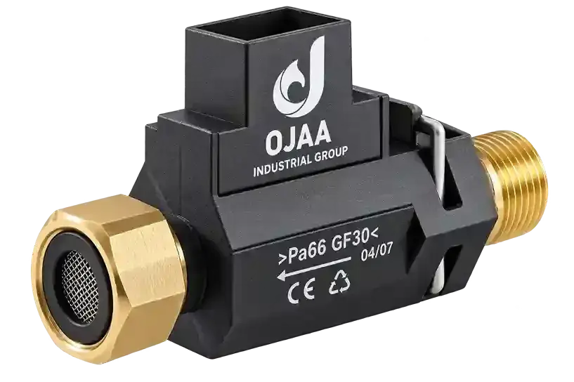
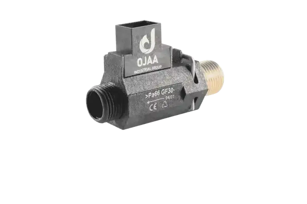
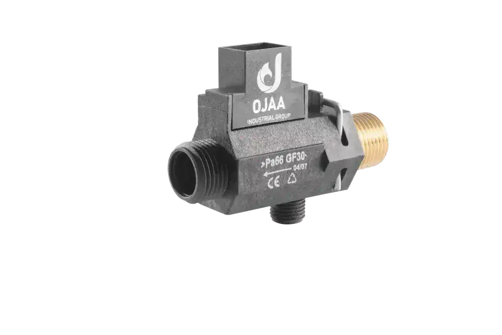
A boiler flow switch operates through an equilibrium of hydrodynamic fluid drag against gravity or a mechanical return spring. Internally, the device features an engineered fluid chamber enclosing a movable polytetrafluoroethylene shuttle carrying an embedded permanent neodymium magnet. When domestic water flow exceeds the calibrated activation threshold—typically set between 1. 5 and 2. 5 liters per minute—the kinetic force of the incoming fluid lifts the shuttle along its travel path. Positioned externally along the non-magnetic composite housing sits a hermetically sealed glass reed switch. When the magnetic field of the elevated shuttle aligns with the reed envelope, the two overlapping ferromagnetic contacts close, producing a dry electrical continuity state. This contact closure pulls a direct-current microswitch channel on the microprocessor to ground or a logic high level. The moment the domestic tap shuts, gravity drops the magnetic float away from the switch, restoring an open-circuit state. The flow switch provides zero data regarding flow volume, line pressure, or fluid velocity; fluid movement is simply verified as active above a fixed limit. In the precision manufacturing facilities of OJAA Industrial Group, flow switches are built across threaded union configurations, two-way linear bodies, and integrated three-way hydroblock manifolds to withstand high static line pressures and dynamic water hammer spikes common in regional municipal water supplies.
Operational Physics of a Boiler Flow Meter and Volumetric Measurement
A boiler flow meter operates as a continuous hydronic turbine sensor paired with a solid-state Hall-effect integrated circuit. Within its wear-resistant polymer casing, incoming fluid impinges on the blades of a radial impeller mounted on low-friction ceramic or stainless-steel pin bearings. Miniature permanent magnets are encapsulated within the turbine structure. As water flows, the rotational frequency of the impeller becomes directly proportional to volumetric flow rate. The external Hall-effect chip detects the alternating magnetic poles sweeping past its sensing face. Operating on external direct-current excitation, the Hall sensor outputs a continuous digital square-wave pulse train whose frequency corresponds directly to instantaneous water throughput. The appliance printed circuit board processes this pulse train within dedicated microcontroller interrupt timers. By calculating the frequency over time, the board determines the exact liters-per-minute rate. This real-time feedback loop informs the microcontroller whether a single washbasin tap is running at minimal flow or multiple showers are drawing maximum capacity simultaneously.
Impact on Burner Modulation and Thermal Stability
The choice between a flow switch and a flow meter profoundly dictates how the boiler modulates its burner: Boilers configured with flow switches: The control board initiates ignition and opens the gas valve to an arbitrary pre-purge ignition level immediately upon reed closure. Subsequent gas valve modulation relies purely on feedback error from domestic hot-water NTC thermistors. Because heat takes several seconds to travel across the secondary plate heat exchanger to the external pipe thermistor, the system suffers thermal inertia. If the user adjusts the shower tap, the boiler experiences delayed modulation, producing noticeable temperature fluctuations. Boilers configured with turbine flow meters: The control architecture applies feed-forward predictive algorithms. Having calculated instantaneous volumetric flow rate before water even exits the heat exchanger, the microprocessor computes the exact thermal energy input required to achieve the set-point temperature using the fundamental thermodynamic enthalpy balance. The modulation coil on the gas valve adjusts in fractions of a second, eliminating domestic temperature spikes and maximizing fuel efficiency.
Detailed Engineering Comparison
A comparison between flow switches and flow meters encompasses several technical parameters: Transduction principle: Flow switches utilize hydrodynamic lift and mechanical reed contacts; flow meters employ turbine rotation and Hall-effect solid-state switching. Output signal profile: Flow switches yield a binary dry contact closure; flow meters generate a continuous square-wave frequency pulse train. Harness terminal count: Flow switches interface through 2 non-polarized conductors; flow meters require 3 conductors comprising positive DC supply, common ground, and digital signal output. Low-flow sensitivity: Flow switches remain inactive beneath their fixed threshold around 2 liters per minute; flow meters measure flow down to 1. 0 to 1. 2 liters per minute. Contaminant susceptibility: Flow switches degrade when suspended magnetite sludge coats the magnetic piston; flow meters lock up when mineral scale or pipe grit lodges between the turbine blades. Electrical vulnerability: Reed switches fail via contact pitting or physical glass fracture; Hall sensors are vulnerable to electrical over-voltage transients and thermal degradation.
Is a Flow Meter Universally Superior to a Flow Switch?
While a turbine flow meter represents a more advanced instrumentation platform, heating engineering relies on matched system integration rather than universal superiority. In basic entry-level combi boilers featuring simple bithemic heat exchangers and unmodulated control loops, a flow meter provides no functional benefit because the firmware cannot process frequency data. Furthermore, flow switches are inherently lower in production cost, consume zero quiescent electrical power during standby, and exhibit complete immunity to electronic power surges. When matched to an appropriate control loop, a well-engineered flow switch provides exceptional, robust reliability over years of service.
Field Identification Procedures for Service Technicians
To determine the flow sensing architecture without access to technical service manuals, technicians should follow these field steps: Inspect harness conductor count: The primary visual indicator is the number of insulated wires entering the sensor plug at the cold-water inlet. A two-wire harness almost universally indicates a mechanical reed flow switch, whereas a three-wire bundle indicates a Hall-effect pulse sensor. Inspect the hydraulic housing geometry: Flow meters feature a rounded turbine chamber with an externally clipped or screwed Hall sensor cartridge. Flow switches display an elongated linear brass or composite cylinder inside which the magnetic piston travels axially. Review digital interface fault codes: Microprocessor-controlled appliances register distinct diagnostic trouble codes for open-circuit flow switch contacts versus missing frequency pulse faults. Evaluate response to low-flow tap adjustments: If opening a tap to a faint trickle produces zero burner activity until the valve is opened wider, the appliance is governed by a flow switch threshold.
Failure Modes and Diagnostic Protocols
Because both devices trigger the domestic heating sequence, failure of either sensor manifests as completely unheated water when a tap opens. Diagnostic separation requires targeted testing: Boiler fails to ignite on demand: For flow switches, common causes include mineral scale jamming the float in its resting base or oxidized reed contacts. For flow meters, failure involves grit seizing the turbine axle or electrostatic destruction of the Hall sensor chip. Boiler continues firing after tap closes: This dangerous condition occurs almost exclusively in flow switches when magnetic debris or limescale pins the float in the elevated position, leaving the reed closed and triggering the high-limit safety thermostat. Turbine flow meters cannot produce continuous pulses once water stops moving. Rapid domestic water temperature cycling: This symptom in flow meter boilers typically points to worn impeller pin bearings, causing erratic rotational speed and fluctuating pulse outputs that confuse the gas modulation loop.
Step-by-Step Multimeter Test for a Boiler Flow Switch
Isolate the combi boiler from mains electrical power and verify zero voltage. Unplug the two-wire harness from the flow switch spade or socket terminals. Switch the digital multimeter to the continuity buzzer mode or low-resistance ohms scale. Attach test probes to the two switch terminals. With all water taps closed, the circuit must register an open circuit with no audible tone. Fully open a domestic hot-water outlet. As water moves through the body, the buzzer must sound continuously, and displayed resistance must fall below 2 ohms. Close the water tap. The continuity tone must cease within one second. Failure to close or open cleanly indicates mechanical sticking or damaged contacts.
Step-by-Step Multimeter Test for a Boiler Flow Meter
Because a Hall-effect flow meter is an active solid-state transducer, evaluation requires an energized control board: Maintain harness connections while accessing terminal pins safely with insulation-piercing probes or back-probes. Select the DC voltage scale and verify the excitation voltage across the positive supply and ground wires, which typically reads a steady 5V DC. Move the positive meter probe to the third conductor carrying the pulse signal, maintaining the black probe on common ground. With water taps closed, the meter will display a static logic state of approximately 0V or 5V DC. Open the domestic hot-water tap. As the turbine rotates, an analog multimeter will vibrate, while a digital meter will display a dynamic average voltage reading between 1. 5V and 3. 5V DC that shifts with changing water flow. If the multimeter features a digital frequency counter, set the dial to Hertz and measure the signal directly; the displayed frequency should scale smoothly upward from tens to hundreds of Hertz in proportion to tap flow rate. Zero Hertz indicates a seized rotor or defective Hall IC.
Feasibility of Substituting a Flow Switch for a Flow Meter
Direct component substitution between a flow meter and a flow switch is technically impossible without replacing the electronic motherboard and reprogramming system firmware. If a flow switch is wired into a control board configured for a flow meter, closing the tap switch presents a static logic level where a dynamic pulse train is expected. The firmware interprets this as a locked rotor and shuts down the burner. Conversely, wiring a three-wire pulse sensor into an unpowered dry-contact input fails to supply excitation voltage to the Hall chip, leaving the circuit dead. The two components are compatible only when servicing an appliance equipped with a universal replacement board that allows the installer to toggle the flow sensor parameter between contact switch and pulse counter via a hidden technician menu.
Technician Evaluation Checklist Before Ordering
Before ordering or replacing a boiler flow component, verify these mechanical and electronic parameters: Control board signal architecture: Confirm whether the microprocessor expects a binary switch contact or a dynamic frequency pulse. Hydraulic manifold interface: Match threaded union connections, push-fit clip seats, or compression couplings. Flow path geometry: Confirm linear two-way inline passages versus integrated three-way manifold blocks. Electrical harness termination: Match socket pinout, wire gauge, and locking latch orientation. Inlet strainer integrity: Inspect the fine stainless-steel mesh filter seated ahead of the sensor to protect the replacement part from pipe rust and grit.
Final Summary
The difference between a boiler flow meter and a flow switch represents two distinct operational philosophies in hydronic engineering. A flow switch acts as an on-off gatekeeper confirming fluid movement, whereas a flow meter serves as a precision volumetric sensor enabling real-time burner modulation and temperature stability. In technical servicing, systematic diagnostics using multimeters and frequency verification prevent incorrect part replacements and maintain the efficiency and safety of wall-hung heating appliances.