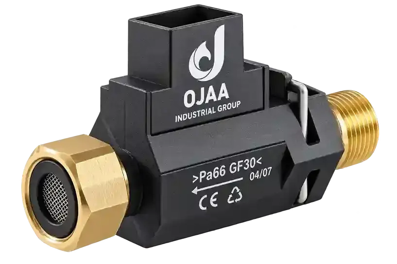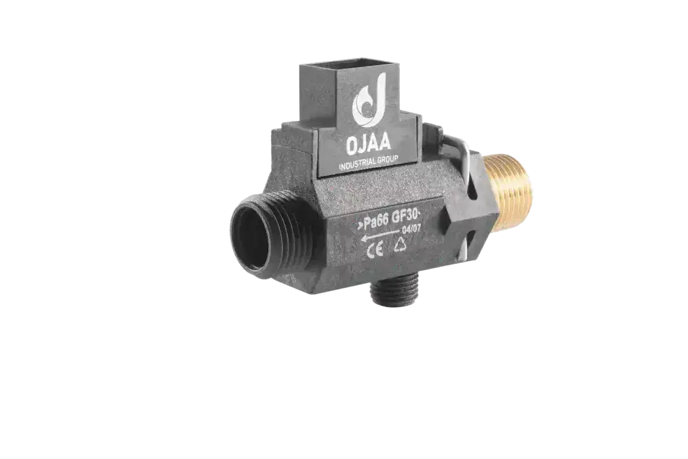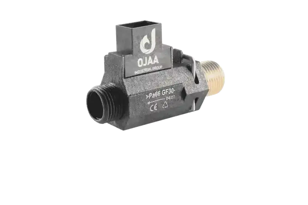
What is a boiler flow meter and how does it advance hydraulic flow monitoring compared to traditional mechanical switches? A boiler flow meter is an active hydronic transducer installed at the cold-water inlet of a wall-hung combi boiler, engineered to measure the continuous volumetric flow rate of sanitary water. A boiler flow meter operates by converting the physical velocity of incoming water into a digital frequency pulse stream via an internal turbine and an external Hall-effect sensor. This telemetry allows the microprocessor to modulate gas burner output dynamically, eliminating hot and cold water fluctuations during domestic showers. In heating component supply chains, terms such as flow sensor, turbine flow meter, and Hall-effect flow sensor denote this active sensing category. Without real-time volumetric measurements, modulating combi boilers cannot achieve stable sanitary temperature delivery. This comprehensive guide details solid-state Hall sensing principles, hydraulic body variants, root causes of turbine jamming, and live multimeter testing procedures.
Operating Principles of Turbine Boiler Flow Meters
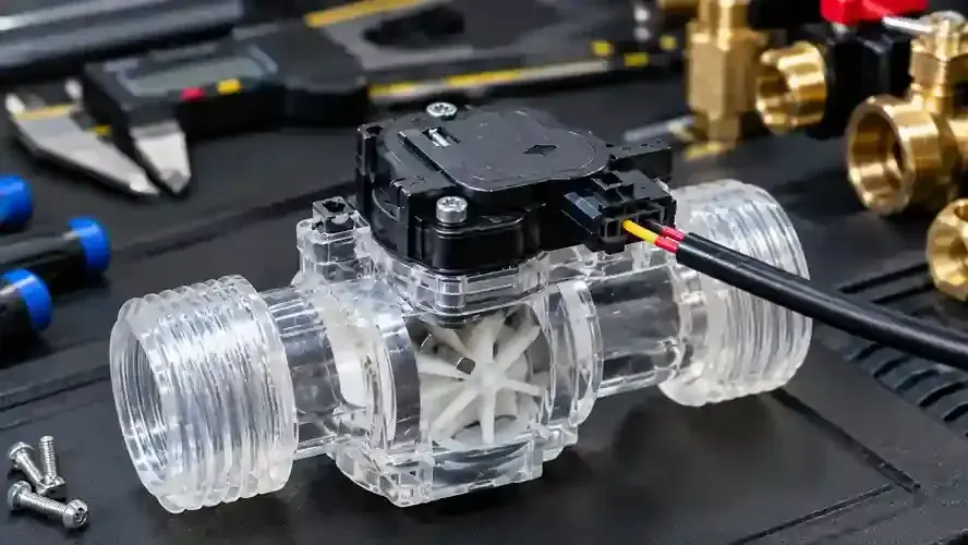
The operational mechanics of a combi boiler flow meter combine hydrodynamic turbine rotation with electromagnetic Hall-effect sensing. The assembly comprises an internal polymer hydroblock housing, a multi-bladed radial impeller, and a stationary Hall-effect integrated circuit mounted externally on the shell. When an occupant opens a domestic hot-water fixture, fluid velocity drives the angled turbine blades into rotational motion directly proportional to flow rate. Embedded within the turbine perimeter are miniature permanent neodymium magnets. As the turbine rotates, these magnetic poles sweep past the external Hall-effect sensor. Energized by a 5. 0V DC excitation rail from the control board, the Hall sensor toggles its output transistor, producing a clean square-wave digital frequency pulse for every passing magnetic field. The boiler microprocessor counts incoming pulse frequency, applying an internal calibration K-factor to compute real-time flow in liters per minute. In quality control assessments conducted at OJAA Industrial Group testing laboratories in Abbasabad Industrial Estate, turbine rotational balance and permanent magnet flux density proved critical to ensuring linear pulse streams free from signal dropout.
Common Hydraulic Architectures of Boiler Flow Meters
Combi boiler manufacturers utilize several mechanical flow meter configurations based on internal hydroblock packaging: Radial and cartridge turbine flow meters: The most common configuration, where a compact cylindrical cartridge containing the turbine is secured inside the composite or brass hydroblock using a retaining clip. Inline linear flow meters: Threaded or clip-retained assemblies engineered with coaxial 180-degree ports installed directly along the cold-water inlet pipe. Integrated flow regulators: Assemblies pairing a turbine rotor with an elastomeric dynamic flow restrictor to cap domestic draw at calibrated maximums, typically between 10 and 14 liters per minute. Dual-polarity Hall sensors: Advanced sensor layouts capable of detecting reverse flow pulses to filter out hydraulic pressure surges in the plumbing grid.
Symptoms of a Defective Boiler Flow Meter
When a flow meter fails or becomes mechanically obstructed, distinct domestic hot-water anomalies emerge: Inactive boiler during tap demand: The burner fails to ignite and no tap demand icon illuminates on the digital display despite high water flow. Erratic shower temperature fluctuations: Worn turbine spindle bearings cause intermittent rotational hesitation, producing erratic frequency drops that induce severe burner hunting. Delayed ignition response: The boiler only fires when multiple taps are opened at maximum volume; this symptom points to limescale accumulation increasing turbine starting torque. Dedicated diagnostic fault codes: Modern digital control boards display specific flow sensor error codes indicating missing pulse feedback. External casing leaks: Degraded EPDM O-rings or cracked polymer housings resulting from winter freezing cause weeping water leaks beneath the appliance.
Root Causes of Flow Meter Jamming and Breakdown
Debris and pipework contamination: In newly commissioned plumbing, loose PTFE tape shreds, pipe scale, and sand enter the hydroblock and wedge between impeller blades. Mineral limescale encrustation: Hard water supplies deposit calcium carbonate layers across the turbine spindle, increasing rotational friction until the rotor seizes. Solid-state Hall element failure: Water weeping past worn internal seals corrodes the sensor socket, shorting the Hall-effect integrated circuit. Rotor magnet fractures: Hydraulic shockwaves from fast-closing lever valves crack the embedded permanent magnets, destroying inductive coupling with the sensor.
Step-by-Step Multimeter Diagnostics
To verify flow meter functionality under live operating conditions, follow this electrical test sequence: Electrical safety and preliminary setup: Keep the boiler energized with the wiring harness connected to the flow meter. Set the digital multimeter to DC volts on the 20V scale. Supply voltage verification: Measure across the power supply and ground pins; the reading must register a stable 5. 0V DC. If power is absent, inspect harness leads and control board regulator circuits. Live signal sweep test: Move the positive probe to the signal output wire while maintaining the negative probe on circuit ground. Active hydraulic verification: Open a domestic hot-water tap to rotate the turbine. The multimeter should display an average switching voltage between 1. 5V and 3. 0V DC. Varying the tap flow rate must produce noticeable shifts in this average DC voltage. Identifying solid-state failure: A signal lead locked permanently at 0. 0V or 5. 0V during active water flow confirms a seized turbine or a defective Hall element. Mechanical spin test: Isolate water, extract the flow meter cartridge, and blow gently across the inlet port; a healthy turbine must spin freely with low acoustic friction.
Technician Evaluation Checklist for Component Replacement
When sourcing a replacement boiler flow meter, verify these engineering factors: Hydroblock port compatibility: Confirm push-fit retaining clip collars versus threaded inline unions. Harness connector pinout: Match the polarity sequence of 5V power, ground, and pulse signal terminals to appliance schematics. Stainless-steel filter mesh: Ensure an intact fine mesh strainer is fitted upstream to protect the impeller from line grit. O-ring elastomer rating: Always fit brand-new, WRAS-compliant EPDM O-rings lubricated exclusively with food-grade silicone grease. Rotor rotational freedom: Verify by manual inspection that the turbine spins completely unhindered prior to manifold insertion.
Final Summary
A boiler flow meter represents the foundation of dynamic temperature control in modern wall-hung combi appliances. Combining precision hydrodynamic turbines with solid-state Hall electronics ensures instantaneous burner response and stable hot-water delivery. Executing disciplined multimeter voltage testing, inspecting filter screens, and confirming pulse signal generation guarantees reliable diagnostics and restores peak domestic heating efficiency.