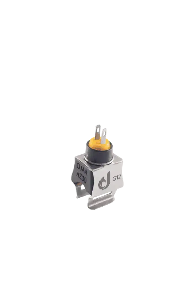
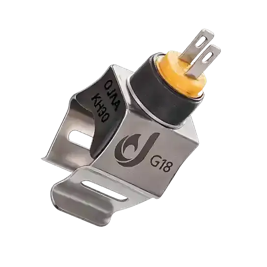
Understanding the operational difference between a boiler central heating vs. DHW NTC sensor is an essential diagnostic step when troubleshooting combi boilers. The primary distinction between a boiler central heating vs. DHW NTC sensor lies in their dedicated hydronic loops: the central heating (CH) thermistor monitors closed-loop primary water circulating through radiators between 30°C and 85°C to control space heating, while the domestic hot water (DHW) thermistor regulates sanitary water exiting the secondary plate heat exchanger between 35°C and 60°C to eliminate erratic shower temperatures. Although both sensors frequently share an identical nominal 10 kΩ rating at 25°C, their control functions and response dynamics differ entirely. Failing to separate these two sensor roles during field maintenance often leads service technicians to replace functional components while leaving the underlying fault unresolved. Analyzing their mechanical locations, control parameters, and electrical profiles ensures precise diagnosis.
Operational Role of the Central Heating (CH) NTC Sensor
The CH thermistor measures fluid temperatures circulating within the primary closed hydronic circuit feeding radiators, fan coils, or underfloor heating manifolds. This water remains isolated within the heating circuit and experiences continuous recirculation through the primary copper heat exchanger.
- Burner modulation in heating mode: The central printed circuit board monitors CH thermistor resistance to scale the gas valve modulating coil, aligning burner output with space-heating demand.
- Anti-frost activation: If primary circuit water drops below approximately 5°C during cold spells, the CH sensor triggers the anti-frost sequence, starting the circulation pump and firing the burner at minimum output.
- Thermal safety and high-limit prevention: By detecting primary flow temperatures approaching 85°C or 90°C, the CH sensor commands burner shutdown before temperatures reach the threshold of manual-reset limit thermostats.
- Anti-cycling timing: The controller uses CH temperature recovery gradients to enforce anti-cycling intervals, preventing rapid on-off burner hunting.
Operational Role of the Domestic Hot Water (DHW) NTC Sensor
The DHW sensor monitors sanitary water exiting the secondary plate heat exchanger directly toward household domestic taps and shower outlets. This water requires precise thermal boundaries to ensure user comfort and prevent scalding.
- Real-time domestic temperature stabilization: When flow switches or turbine flow meters confirm tap opening, the DHW sensor reports thermal output gradients to establish burner modulation, matching target setpoints.
- Anti-scalding thermal cutoff: Sanitary water parameters are constrained between 35°C and 60°C; the control board suppresses burner firing if secondary water approaches dangerous temperatures.
- Dynamic compensation for flow variations: When tap opening rates shift or incoming mains water pressure fluctuates, the DHW thermistor must register transient temperature swings rapidly, directing the gas valve to adapt fuel delivery.
Engineering Comparison: CH vs. DHW Thermistors
While operating under identical negative temperature coefficient principles, their operational environments and hardware requirements differ:
- Hydraulic installation point: The CH sensor mounts onto the copper flow pipe leaving the primary heat exchanger; the DHW sensor installs at the sanitary hot-water outlet of the secondary plate heat exchanger.
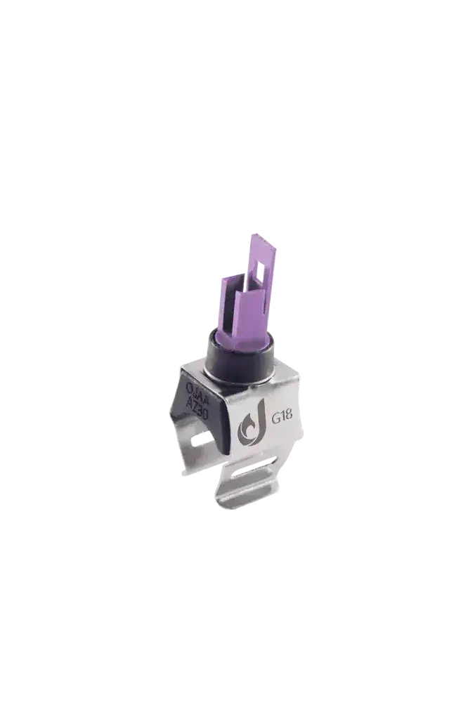
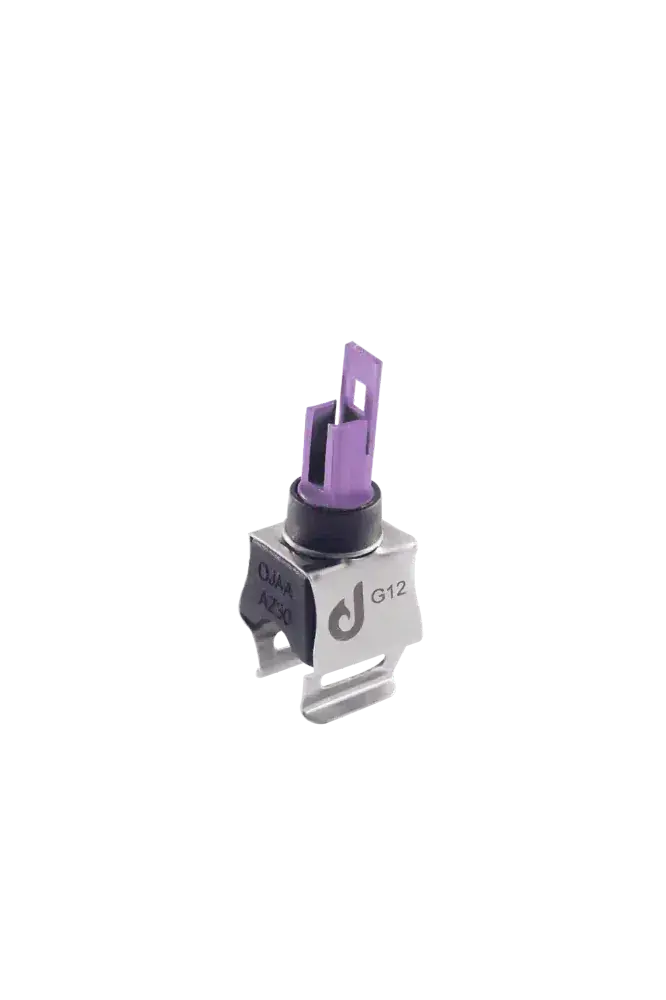
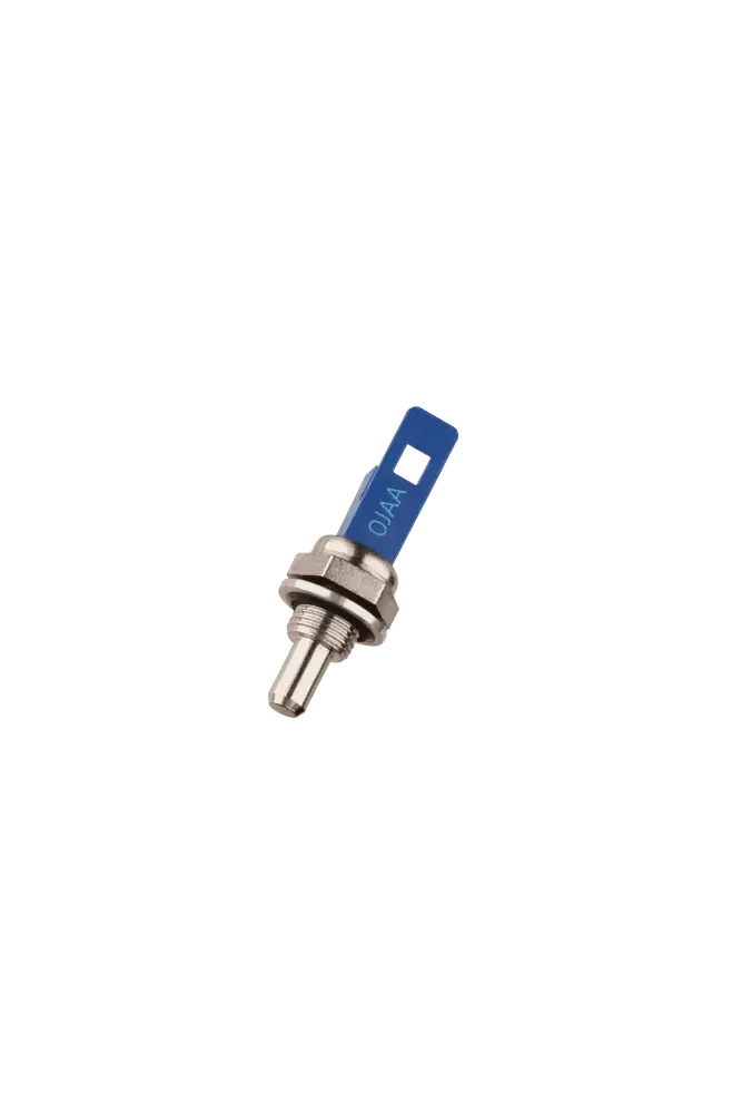
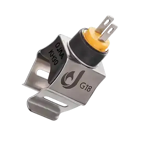
- Mechanical contact interface: CH sensors are commonly surface clip-on designs gripping pipe exteriors; DHW sensors frequently utilize wet-pocket immersion brass probes to maximize conduction speed.
- Calibrated operational span: The CH circuit operates between 30°C and 85°C; the DHW circuit functions between 35°C and 60°C.
- Thermal response velocity: DHW sensors prioritize low thermal mass for millisecond response times to prevent cold shower slugs; CH sensors employ moderate response dampening to prevent hunting from radiator return surges.
- Diagnostic trouble codes: Control board microprocessors assign unique fault codes for CH circuit open/short states versus DHW circuit failures.
Divergent Failure Symptoms: Central Heating vs. Sanitary Hot Water
Because the electronic control board isolates these feedback channels, symptoms resulting from sensor failure manifest in distinct system behaviors: Symptoms of a failed CH NTC sensor:
- Radiators remain lukewarm despite the boiler firing, or overheat well beyond thermostat settings.
- The burner cycles rapidly on and off every few seconds when operating in winter mode.
- The user interface displays dedicated heating-circuit fault codes while the radiator symbol flashes.
- The circulation pump runs continuously in anti-frost mode without active heating demand.
- Domestic hot-water production often continues operating normally with steady tap temperatures.
Symptoms of a failed DHW NTC sensor:
- Domestic hot water cycles erratically between scalding hot and freezing cold during showers, while radiators heat normally.
- Opening hot-water taps causes the boiler to ramp to boiling point and shut down on overheat, or fails to raise tap water above mains cold levels.
- The boiler fails to stabilize water temperature under changing tap flow rates.
- The display interface registers dedicated sanitary sensor failure codes.
Can CH and DHW Sensors Be Interchanged?
If both sensors share the same mechanical form factor—such as identical clip-on diameters—and identical electrical characteristics of 10 kΩ at 25°C and matching Beta constants, they can serve in either position. Standardized component architectures, like those manufactured by OJAA, allow uniform clip-on sensors to be applied to either circuit when parameters match. However, interchangeability is impossible if physical mounting architectures differ. Installing an external clip-on sensor where an immersion probe is required leaves open hydraulic ports. Furthermore, certain European appliances employ different Beta constants or distinct nominal values—such as 10 kΩ for CH and 12 kΩ or 50 kΩ for DHW. Interchanging electrically mismatched sensors disrupts algorithmic modulation, causing ongoing temperature control faults.
The Cross-Diagnostic Swap Method for Field Technicians
When diagnosing an appliance where both sensors share identical mechanical and electrical ratings, technicians can utilize the cross-swap diagnostic procedure:
- Isolate the combi boiler from mains electrical power.
- Disengage the electrical harness plugs from both the CH and DHW sensors.
- Provided harness leads permit adequate reach, connect the CH wiring harness to the DHW sensor and the DHW harness to the CH sensor.
- Restore power and observe the resulting fault behavior.
If the active diagnostic trouble code shifts from the heating circuit to the sanitary circuit, the fault is isolated to a failed thermistor element. If the fault remains registered on the original circuit, the sensors are functional and the failure originates within wiring harnesses, terminal oxidation, or control board voltage-divider circuits.
Step-by-Step Multimeter Diagnostics for CH and DHW Sensors
Verifying thermistor health requires controlled resistance measurements:
- Power down the appliance and disconnect mains electricity.
- Unplug electrical connections from both sensors to isolate them from control board circuitry.
- Set the digital multimeter to the resistance scale at the 20 kΩ setting.
- Connect test probes across the terminals of the CH sensor and record resistance alongside ambient room temperature; at 25°C, reading should sit near 10 kΩ.
- Connect test probes to the DHW sensor terminals under identical ambient conditions; both sensors should measure within a 5 percent tolerance of each other if rated identically.
- Apply indirect heat to each sensor shoe or immersion probe; resistance must decline smoothly without open-circuit breaks or sudden fluctuations.
Technician Evaluation Checklist for Sensor Selection
When ordering or installing replacement thermistors, verify these engineering factors:
- Hydraulic interface: Confirm whether the installation calls for surface clip-on or threaded immersion probes.
- Base nominal resistance: Verify calibrated resistance at 25°C against appliance technical documentation.
- Beta sensitivity constant: Ensure identical temperature-resistance curve parameters to avoid modulation drift.
- Mechanical conduit or thread sizing: Check G12 or G18 clip dimensions for pipe contact, or thread pitch for immersion models.
- Harness terminal style: Match polarized plastic multi-pin sockets or spade terminals to existing harnesses.
- Thermal shoe integrity: Clean pipe contact surfaces down to bare copper before seating clip-on thermistors.
Final Summary
Mastering the technical differences between boiler central heating vs. DHW NTC sensors establishes an accurate foundation for combi boiler diagnostics. The CH sensor stabilizes primary hydronic loops and safety cutoffs, while the DHW sensor controls dynamic sanitary hot-water comfort. Verifying mounting styles, matching electrical Beta coefficients, and conducting multimeter resistance tests prevents misdiagnosis and guarantees long-term heating efficiency.