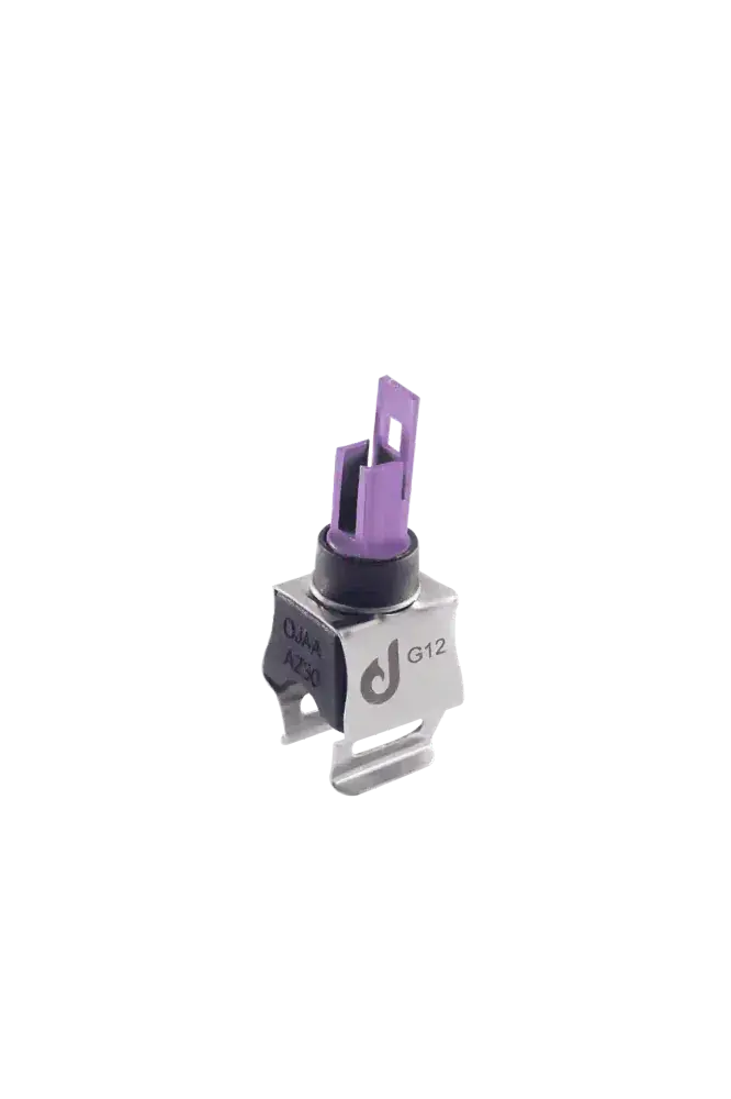
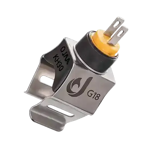
Understanding what a boiler NTC sensor is and how it regulates combustion is a fundamental requirement in heating system diagnostics. A boiler NTC sensor is a ceramic semiconductor thermistor possessing a negative temperature coefficient, engineered to monitor fluid temperatures across primary heating and domestic hot-water circuits. As water temperature rises, internal electrical resistance declines along a defined logarithmic curve. The boiler control board measures this variable resistance across a voltage-divider circuit to modulate the gas burner dynamically. In modern condensing and conventional combi boilers, a minor resistance drift within the thermistor alters electronic calculations, causing chronic domestic hot-water temperature swings or sudden primary lockouts. Mastering the non-linear relationship between temperature and resistance, separating sensor degradation from wiring harness corrosion, and executing structured bench testing prevents misdiagnosis during service interventions. This technical guide explores thermistor physics, clinical failure signs, and field multimeter verification steps.
How Does a Boiler NTC Thermistor Measure Temperature?
The operating mechanics of an NTC thermistor depend on transition metal oxides—such as manganese, nickel, and cobalt—sintered into a dense polycrystalline ceramic element. As thermal energy enters the semiconductor lattice, valence electrons gain sufficient energy to cross the bandgap into the conduction band, increasing electrical conductivity and driving resistance downward. The boiler control board supplies a regulated 5. 0V DC excitation rail across a precision voltage-divider circuit. As the thermistor resistance shifts, the analog voltage drop across its terminals shifts proportionally, entering the microcontroller analog-to-digital converter (ADC). Using the Steinhart-Hart equation and calibrated lookup tables stored in firmware, the microprocessor translates this voltage into an exact Celsius temperature. During manufacturing at OJAA Industrial Group production facilities located in Abbasabad Industrial Estate, nominal base resistance—standardized at 10 kΩ at 25°C—and the material sensitivity constant (Beta value) undergo rigorous batch validation to eliminate measurement drift across operational lifespans.
10K Resistance vs. Temperature Calibration Profile
The characteristic logarithmic resistance curve of a standard 10 kΩ combi boiler thermistor tracks across distinct temperature thresholds: 0°C (freezing threshold or mains cold): Nominal resistance measures approximately 27 kΩ to 32 kΩ. 10°C (winter municipal mains baseline): Nominal resistance measures approximately 19 kΩ to 21 kΩ. 25°C (calibrated reference baseline): Calibrated nominal resistance reads exactly 10. 0 kΩ with a 1% to 5% tolerance. 40°C (optimum domestic hot-water delivery): Nominal resistance measures approximately 5. 0 kΩ to 5. 5 kΩ. 60°C (standard space heating radiator flow): Nominal resistance measures approximately 2. 2 kΩ to 2. 6 kΩ. 80°C (maximum primary circuit output): Nominal resistance measures approximately 1. 1 kΩ to 1. 3 kΩ. Significant deviations from these benchmark values confirm internal lattice degradation or permanent calibration drift.
Immersion vs. Surface Clip-On Sensor Architectures
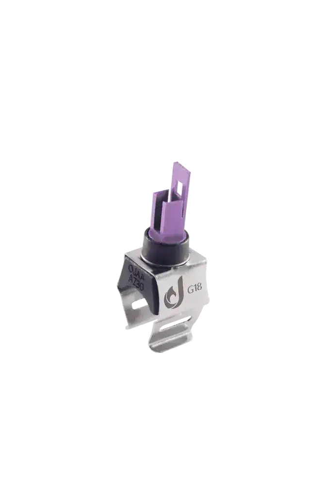
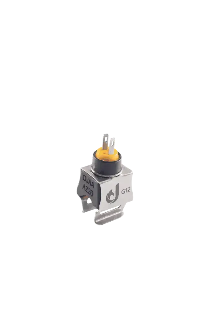
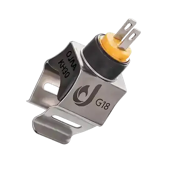
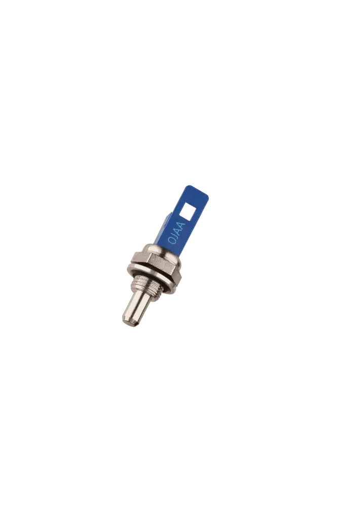
Combi appliances utilize two distinct mechanical NTC mounting profiles: Wet-pocket immersion NTC sensors: The brass or stainless-steel probe threads directly into the hydraulic manifold, making direct physical contact with circulating water. This architecture provides millisecond thermal response times, ideal for domestic hot-water modulation. Surface clip-on NTC sensors: The thermistor mounts externally on copper tubing via a high-tensile spring clip. Heat transfers across an electroplated contact shoe. Servicing requires no circuit draining, though surface cleanliness and thermal paste application remain mandatory. Sealing integrity and clamping force: Immersion sensors require WRAS-compliant EPDM O-rings to prevent weeping leaks under municipal pressure, while clip-on variants rely on spring tension to eliminate air gaps.
Clinical Symptoms of a Defective Boiler NTC Sensor
Sensor failure distorts feedback loops, producing distinct operating anomalies: Domestic hot-water temperature swings: Shower water cycles erratically between scalding and cold as the board hunts over-reactively due to delayed sensor feedback. Lukewarm radiators during active firing: The sensor produces an artificially low resistance reading; the board misinterprets the circuit as hot, throttling burner output prematurely. Rapid short-cycling: The burner fires and extinguishes in rapid multi-second cycles due to irregular voltage spikes across deteriorated thermistor pins. Dedicated diagnostic trouble codes: The control board registers sensor open-circuit or short-circuit lockouts on the user interface. Unwarranted anti-frost activation: A cracked thermistor generating artificially high resistance tricks the board into registering sub-zero water, running the circulation pump continuously.
Root Causes of Thermistor Failure and Resistance Drift
Cyclic thermal fatigue: Relentless thermal cycling between 20°C and 85°C induces mechanical micro-fractures within the ceramic semiconductor body, shifting the material Beta constant. Internal moisture ingress: Condensation tracking along lead wires breaches epoxy coatings, creating parallel conductive paths that distort resistance readings downward. Mineral limescale encrustation: Hard water deposits heavy calcium carbonate layers across immersion probe bodies, acting as an insulating jacket that delays heat transfer. Terminal pin fretting and corrosion: High humidity inside the chassis corrodes harness terminals, introducing uncalibrated contact resistance.
Step-by-Step Multimeter Diagnostics
To verify thermistor integrity accurately, follow this diagnostic sequence: Electrical isolation: Power down the combi boiler and disconnect mains electricity. Allow hydraulic pipework to cool toward room temperature. Terminal disconnection: Unplug harness connectors from the sensor terminals. Never measure resistance while leads remain wired to the control board. Meter configuration: Set the digital multimeter to the resistance scale at the 20 kΩ range. Ambient baseline check: Attach meter probes across the two sensor pins while simultaneously measuring ambient air temperature. At approximately 25°C, the reading should register within factory tolerance of 10 kΩ. Dynamic thermal excitation: Submerge the sensing tip into warm water or grip the metal contact shoe between warm fingers. Observe resistance decay: Displayed resistance must decline smoothly, continuously, and logarithmically without jumping, dropping to zero, or reading open circuit. Thermal relaxation verification: Remove the heat source; the resistance reading must climb steadily back toward the initial ambient baseline.
Technical Distinction: NTC vs. Platinum RTD and High-Limit Thermostats
Clear boundaries must be maintained among heating sensors: Distinction from Platinum RTDs: Industrial RTD sensors (such as PT100) exhibit a positive temperature coefficient (PTC) where resistance climbs with heat; combi boiler microprocessors cannot interpret RTD signals. Distinction from high-limit thermostats: A high-limit cutoff is a binary mechanical switch that snaps open at 105°C to kill gas valve power; it provides no analog resistance curve. Wiring polarity: NTC thermistors are non-polarized resistive devices; reversing lead connections during replacement does not alter circuit functionality.
Technician Evaluation Checklist for Component Replacement
When sourcing a replacement boiler NTC thermistor, verify these parameters: Mechanical mounting format: Confirm threaded immersion probes versus surface clip-on collars. Conduit diameter matching: For clip-on models, match G12 (1/2-inch) or G18 (3/4-inch) dimensions precisely. Nominal resistance and Beta value: Match 10 kΩ at 25°C and corresponding Beta constants (such as 3977 K) to factory specifications. Harness terminal style: Match polarized locking socket shrouds or flat spade blade dimensions. Sealing O-ring condition: Fit fresh, silicone-lubricated EPDM O-rings on all immersion replacements.
Final Summary
A boiler NTC sensor is the primary intelligence source governing heating efficiency and sanitary hot-water stability in wall-hung combi appliances. Understanding the negative temperature coefficient logarithmic curve, verifying resistance against calibrated temperature tables, and distinguishing active thermistors from safety switches prevents diagnostic errors. Meticulous multimeter testing and selecting components verified for thermal stability ensures uncompromised combustion modulation and long-term heating comfort.