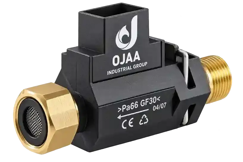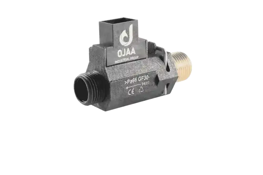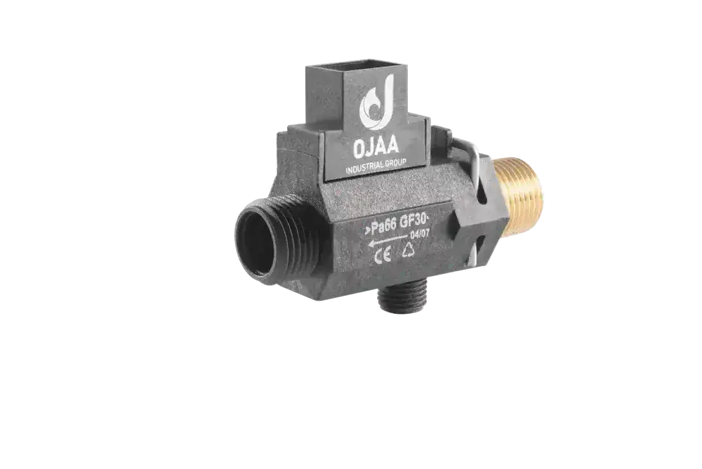
What is a boiler pressure switch and what functional role does it perform in heating appliance safety loops? A boiler pressure switch is an electromechanical safety interlock engineered to monitor fluid pressures and change its electrical contact state when pressure crosses a predetermined operating threshold. Unlike continuous analog transducers, this device functions as a binary hardware switch, informing the main boiler control board whether hydronic or pneumatic conditions are safe to initialize or maintain combustion. In the spare parts sector, technicians frequently encounter ambiguity regarding pressure devices. The terms water pressure switch, differential air pressure switch, flue proving switch, and analog pressure transducer are often confused. This lack of differentiation causes improper part sourcing and repeated diagnostic lockouts. This comprehensive guide examines operating mechanics, pneumatic versus hydronic roles, multimeter verification steps, and root causes of pressure switch lockouts.
How Does a Boiler Pressure Switch Operate?
A boiler pressure switch converts fluid force into a mechanical contact change using an internal elastomeric diaphragm. The diaphragm divides the internal chamber into two isolated pneumatic or hydronic compartments, interfacing mechanically with a sensitive electrical microswitch. When incoming fluid pressure deflects the diaphragm against an internal calibration spring, an actuating pin shifts the microswitch contacts across Common (COM), Normally Open (NO), and Normally Closed (NC) terminals. When pressure declines below the reset differential threshold, the internal spring drives the diaphragm back to its resting geometry. This binary transition signals the boiler microprocessor whether operating thresholds are satisfied. In technical evaluations conducted at OJAA Industrial Group manufacturing laboratories located in Abbasabad Industrial Estate, elastomer elasticity and microswitch contact plating integrity proved essential to preventing contact chatter and contact resistance drift under continuous cyclic operation.
Key Differences: Water Pressure Switch vs. Air Pressure Switch
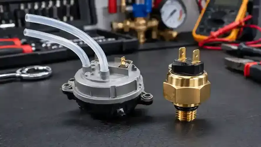
Water and air pressure switches perform entirely different safety functions across distinct operating environments: Fluid environment: A water pressure switch interfaces directly with heating circuit water; an air pressure switch monitors combustion air, room-sealed drafts, and exhaust flue gases. Measurement units and operational span: Water pressure switches operate within hydronic ranges of 0. 4 to 0. 6 bar (40, 000 to 60, 000 Pascals); air pressure switches operate across microscopic differential spans of 20 to 100 Pascals (fractions of a millibar). Physical installation point: Water switches mount directly onto brass or composite hydroblock manifolds; air pressure switches mount at the highest chassis point adjacent to the flue fan. Mechanical port connections: Water switches utilize threaded fittings or retaining spring clips; air switches connect via flexible silicone impulse tubing linked to a fan venturi. Safety interlock function: Water switch failure prevents pump circulation and dry-firing; air switch failure halts spark ignition to prevent carbon monoxide accumulation.
Operating Principles of Differential Air Pressure Switches
The differential air pressure switch is mandatory on room-sealed, fan-assisted combi appliances. It features two impulse ports labeled positive (high pressure) and negative (low pressure/vacuum). When the combustion exhaust fan runs, air forced through an internal constriction called a venturi generates localized static pressure drops based on the Bernoulli principle. Flexible silicone tubes transmit this differential pressure to opposite sides of the internal diaphragm. When differential pressure exceeds the rating stamped on the housing (such as 60/45 Pa), the diaphragm deflects and snaps the microswitch contacts closed. This verifies to the control board that the flue chimney is unobstructed, the fan operates at rated RPM, and combustion products vent safely outside before gas valves open.
Pressure Switches vs. Analog Pressure Transducers
Distinguishing between binary switches and active electronic transducers prevents diagnostic errors during field servicing: Binary pressure switch: An electromechanical device operating without external DC power, providing binary continuity states at fixed mechanical thresholds. Electronic pressure transducer: An active, three-wire solid-state instrument utilizing a piezoresistive ceramic diaphragm to deliver a continuous analog voltage (typically 0. 5V to 3. 5V DC) proportional to water pressure. Hardware interchangeability: Because their interface electronics and control board firmware expectations differ entirely, mechanical switches cannot substitute for active transducers.
Diagnostic Symptoms of Faulty Pressure Switches
When pressure switches fail or system parameters drift, distinct operating anomalies appear: Symptoms of Air Pressure Switch Faults: Fan runs continuously with zero ignition attempt: The exhaust fan runs indefinitely, but the spark electrode never activates because the air switch contact remains open. Flue gas fault code lockouts: Appearance of dedicated error codes such as 40-60-70 or 40-60-80 on Iran Radiator models, E03 on Butane appliances, or E05 on Lorch combi boilers. Flame extinction during active firing: Strong outdoor wind gusts down the terminal pipe or fan motor thermal drift breaks the differential threshold, extinguishing the flame mid-cycle. Welded microswitch contacts: If electrical contacts remain welded shut before the fan energizes, the control board detects an illegal closed state and prevents fan startup. Symptoms of Water Pressure Switch Faults: Low-water error lockouts despite adequate system pressure: The physical pressure gauge reads 1. 5 bar, but the boiler locks out because the mechanical switch remains open. Refusal to energize the circulation pump: The system prevents pump operation to protect impeller bearings from dry cavitation.
Step-by-Step Multimeter Diagnostics
Accurate field evaluation requires systematic electrical verification: Hydronic Water Pressure Switch Testing: Unplug harness connectors from the water pressure switch. Set the digital multimeter to continuity beeper mode. With heating circuit pressure above 1. 0 bar, attach meter probes across the two terminals. The meter must emit a continuous tone indicating zero ohms resistance. Bleeding circuit pressure below 0. 5 bar must break continuity instantly. Pneumatic Air Pressure Switch Live Testing: Initiate a boiler heating cycle so the exhaust fan runs. With the fan spinning, carefully monitor continuity or DC voltage across the COM and NO terminals. If the contact fails to close, disconnect the silicone tubing and apply a gentle, controlled vacuum with a clean plastic syringe while listening for a distinct microswitch click. If manual vacuum triggers continuity but fan operation does not, the switch is functional and the problem lies in the venturi, fan, or flue path.
External Factors Mimicking Pressure Switch Failure
In over 70 percent of flue-related service callbacks, the pressure switch itself is fully functional, with external anomalies tripping the loop: Melted or cracked fan venturi nozzles caused by excessive heat exchanger temperatures. Condensation water droplets accumulated inside the silicone impulse tubing, blocking differential pressure transfer. Flue terminal obstruction caused by external bird nesting, debris, or improper terminal slope. Deteriorated fan motor starting capacitors causing lower impeller rotational velocity. Heavy dust accumulation clogging the venturi dynamic pressure orifices.
Technician Evaluation Checklist for Component Replacement
When sourcing a replacement pressure switch, verify these technical parameters: Application domain verification: Confirm whether the installation calls for a hydronic water switch or a pneumatic air proving switch. Pneumatic trip ratings in Pascals: Match precise cut-in and cut-out values stamped on air switch housings (such as 60/45 Pa or 70/50 Pa). Terminal contact architecture: Confirm two-pin simple continuity or three-pin SPDT layouts featuring Normally Closed contacts. Pressure port configurations: Match single-hose or dual-hose pneumatic connections. Hydronic port specifications: Check thread sizing, union-nut fittings, or push-fit clip collars, fitting fresh EPDM O-rings for water seals.
Final Summary
A boiler pressure switch provides essential binary fail-safe protection across hydronic circulation and combustion ventilation loops. Clearly separating low-water cutoff switches from differential air switches and continuous transducers prevents misdiagnosis. Disciplined multimeter continuity testing, venturi inspection, and pneumatic path evaluation ensures reliable fault isolation and maintains safe heating operation.