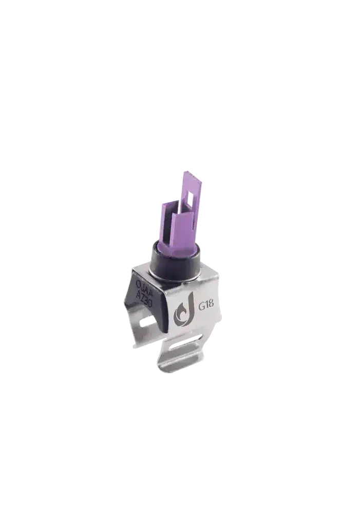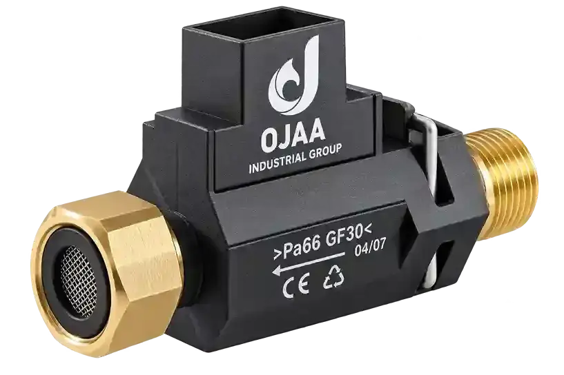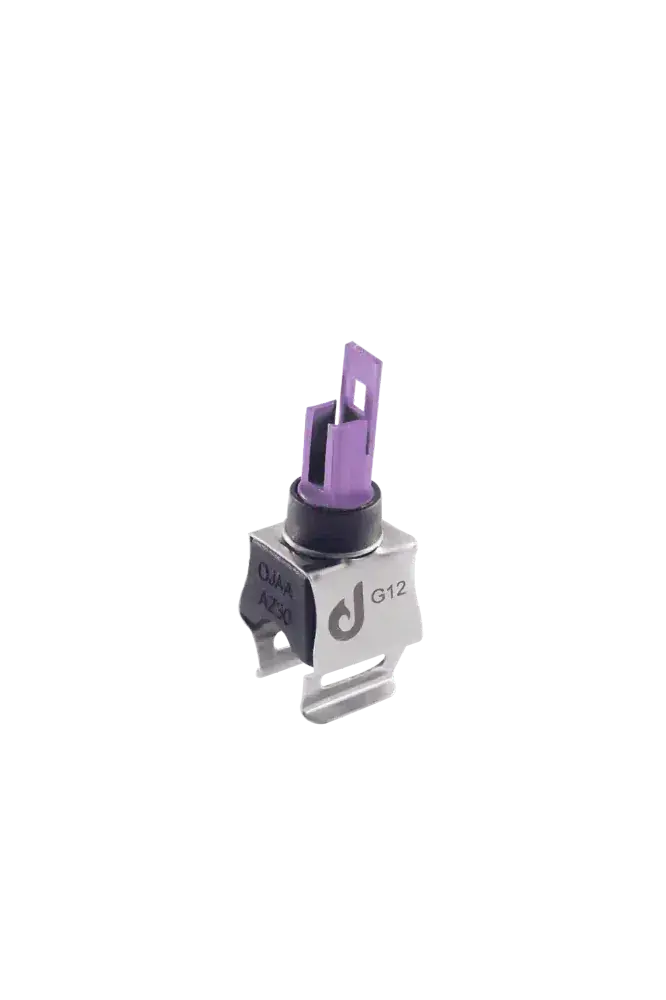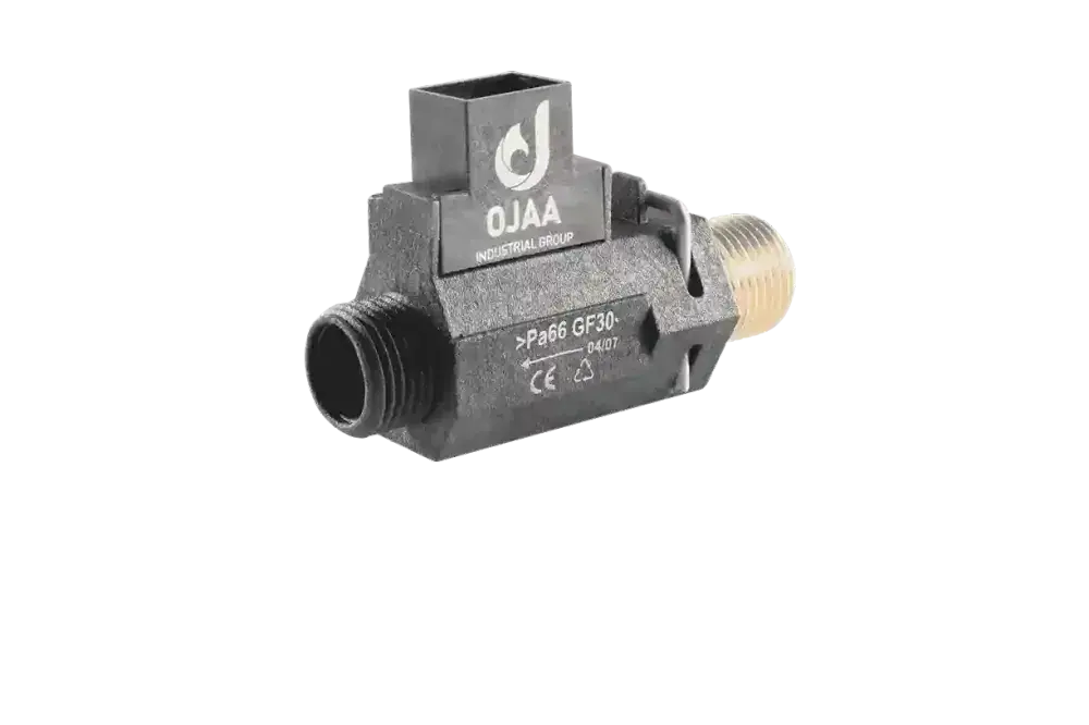
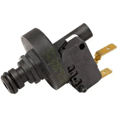
A boiler water pressure sensor is an advanced electronic safeguard engineered to monitor static and dynamic hydronic pressure within closed-loop central heating circuits. Operating as an active three-wire piezoresistive transducer, this component measures system pressure across a calibrated span from 0 to 4 bar. The transducer converts physical fluid force into a proportional analog direct-current voltage, transmitting live data directly to the central printed circuit board microprocessor. This continuous feedback enables contemporary heating appliances to display precision numeric readouts on digital interfaces, generate preventive low-water warnings before complete lockout occurs, and inhibit gas burner ignition during dry conditions. Understanding how this sensing unit functions and mastering its electrical verification prevents unnecessary part replacements during service calls.
How Does a Boiler Water Pressure Transducer Operate?
The transducer interfaces directly with the heating circuit manifold inside the appliance hydroblock. The sensing element comprises a micro-machined ceramic diaphragm integrated with piezoresistive strain gauge elements configured in a Wheatstone bridge circuit. When fluid pressure exerts force against the ceramic face, microscopic deflection alters the internal electrical resistance of the bridge elements. The boiler control board supplies a regulated reference excitation voltage—typically 5. 0V DC—across the power pins. Internal conditioning electronics convert bridge resistance shifts into an analog output voltage. At zero bar gauge pressure, the output registers at approximately 0. 5V DC. As hydraulic pressure climbs linearly toward standard working thresholds around 1. 5 bar, the signal scales smoothly upward toward 1. 8V to 2. 0V DC. The appliance microprocessor translates this voltage curve into real-time bar metrics on the display. In laboratory performance tests conducted at OJAA Industrial Group facilities in Abbasabad Industrial Estate, maintaining a stable 5V rail from the board voltage regulator proved essential to ensuring sensor measurement linearity and preventing false low-pressure shutdowns.
Technical Distinction from Mechanical Binary Switches
Distinguishing between analog transducers and conventional on-off switches prevents diagnostic confusion during maintenance:
- Signal profile: The transducer provides a continuous analog voltage curve tracking pressure fluctuations; binary pressure switches simply open or close a mechanical electrical contact at a fixed setpoint.
- Interface telemetry: Electronic sensors supply decimal numeric values directly to digital screens; mechanical switches cannot report quantitative data, requiring a separate dial manometer.
- Wiring requirements: Active transducers require a 3-wire harness representing DC supply, ground, and analog signal lines; mechanical switches operate as passive 2-wire dry contacts without external power.
- Firmware safety integration: Systems with electronic transducers flash warning alerts at 0. 8 bar and signal overpressure warnings at 2. 8 bar; switch-based systems execute immediate hard shutdowns only after pressure drops below critical limits.
Symptoms of a Defective Boiler Pressure Transducer
When an analog transducer experiences electronic breakdown or port restriction, specific operational faults emerge:
- Static or zero bar readout on the digital interface: The display indicates 0. 0 bar and registers a low-water fault, even though the manual fill loop is open and the system is fully pressurized.
- Inability to clear low-pressure error codes: The appliance remains locked in safety shutdown despite physical water pressure resting at the optimum 1. 5 bar level on external gauges.
- Calibration drift and relief valve discharge: The sensor under-reports true pressure due to internal component drift; the technician overfills the system, causing the 3. 0 bar mechanical safety valve to discharge.
- Fluid weeping inside the electrical plug: Internal diaphragm rupture forces pressurized heating water into the terminal socket, corroding harness pins and threatening board circuits.
- Erratic pressure jumping: Displayed pressure values fluctuate erratically across wide ranges in fractions of a second due to internal resistor cracking.
Primary Causes of Transducer Degradation
Continuous contact with circulating heating water exposes the transducer to several operational hazards:
- Magnetite and sludge contamination: Closed heating circuits generate black iron oxide sludge. Fine debris accumulates inside the narrow fluid entry port, isolating the ceramic diaphragm from system pressure.
- Dynamic water hammer spikes: Rapid valve actuation produces hydraulic shockwaves that crack fragile ceramic sensing diaphragms.
- Power rail instability: Fluctuations or noise on the regulated 5V DC power rail from an aging control board disrupt internal sensor calibration or damage processing integrated circuits.
Step-by-Step Multimeter Diagnostics
Because an electronic pressure sensor is an active instrument, verification requires live DC voltage measurements:
- Terminal inspection: Disengage the harness plug and inspect terminals for moisture, bent pins, or green copper oxide corrosion. Wet terminals indicate internal diaphragm failure.
- Supply voltage verification: Set the digital multimeter to DC volts. Power on the appliance and measure across the supply and ground leads; the reading must register 5. 0V DC with a maximum deviation of 0. 2V. Absence of voltage indicates a wiring harness break or a defective control board regulator.
- Baseline measurement at zero bar: Depressurize the appliance heating circuit to zero bar. Measure voltage between ground and the signal output pin; the baseline must read between 0. 45V and 0. 55V DC.
- Dynamic sweep during pressurization: Slowly open the boiler filling loop to admit water. As system pressure climbs from zero to 1. 5 bar, output voltage must rise smoothly from 0. 5V up to approximately 1. 8V to 2. 0V DC without erratic jumps.
- Diagnostic conclusion: Output voltages locked permanently at 0V, 5V, or failing to respond to rising water pressure confirm an obstructed inlet port or internal electronic failure.
Safe Maintenance for Obstructed Sensor Ports
If a sensor fails to respond due to sludge blockage, field recovery is often possible: Isolate power, drain the appliance, and extract the transducer. Visually inspect the entry port. If black magnetite sludge blocks the aperture, flush it under a gentle stream of clean water using a plastic syringe. Never probe inside the aperture using metal needles, drills, or screwdrivers; physical contact with the thin ceramic diaphragm will instantly puncture it, permanently destroying the instrument.
Evaluation Checklist for Component Replacement
When sourcing a replacement pressure transducer, verify these parameters:
- Mechanical connection interface: Confirm clip-retained push-fit housings or threaded fittings.
- Calibrated operational span: Match the pressure range, typically 0 to 3 bar or 0 to 4 bar.
- Signal output scale: Verify 5V DC power supply with a calibrated 0. 5V to 3. 5V linear output curve.
- Electrical connector profile: Match terminal spacing, polarity keys, and latching mechanisms to the wiring loom.
- Sealing O-ring condition: Install a new WRAS-compliant EPDM O-ring lubricated with silicone grease to eliminate future weeping leaks.
Final Summary
A boiler water pressure sensor provides precision electronic telemetry essential for contemporary hydronic safety. Its continuous analog output, digital diagnostic communication, and preventive fault reporting distinguish it from conventional binary switches. Verifying the 5V power supply, monitoring signal linearity with a multimeter, and avoiding mechanical damage to the ceramic diaphragm ensures dependable troubleshooting and long-term heating reliability.