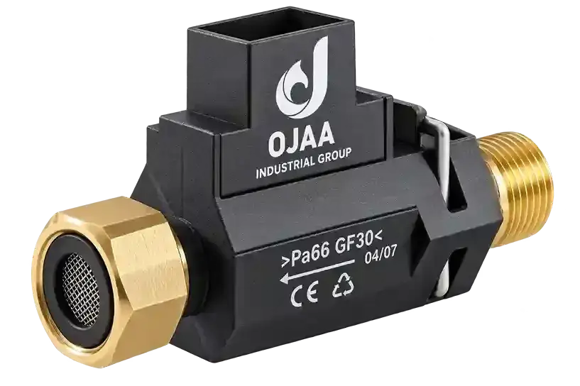
Testing a boiler pressure sensor with a multimeter is an essential diagnostic procedure when troubleshooting combi boilers that suffer from persistent low-water lockouts or frozen digital pressure readings. Testing a boiler pressure sensor with a multimeter cannot be accomplished using a basic continuity buzzer or resistance test. Because contemporary pressure transducers are active electronic instruments, field verification requires measuring regulated direct-current supply voltages and tracking proportional analog signal outputs generated by an internal piezoresistive Wheatstone bridge under dynamic hydraulic pressures. When a boiler display registers a low-pressure fault—such as error F37, E04, 40-70, or flashing low-bar icons—replacing components blindly is inefficient. The technician must systematically verify whether the transducer has failed internally, whether the narrow sensing aperture is choked with iron oxide magnetite sludge, or whether the 5V analog-to-digital converter (ADC) power rail on the main control board has collapsed. This service guide provides the bench and field diagnostic sequence.
Pinout Configuration and Electrical Architecture
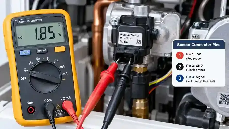
The electrical interface of a contemporary boiler water pressure transducer comprises three dedicated leads:
- Positive 5V DC excitation line: Delivers regulated 5. 0V direct-current power from the control board regulator to energize the internal Wheatstone bridge.
- Ground reference line: The zero-volt return path connected directly to the control board circuit ground.
- Analog signal output line: The conditioned output lead from the internal piezoresistive bridge, delivering an analog voltage between 0. 5V and 3. 5V DC proportional to water pressure.
In technical evaluations conducted at the OJAA Industrial Group quality control laboratories located in Abbasabad Industrial Estate, baseline calibration confirms that zero bar gauge pressure produces approximately 0. 45V to 0. 55V DC on the signal lead. As hydronic pressure increases, the signal voltage scales upward in a linear progression, reaching approximately 1. 8V to 2. 0V DC at the standard 1. 5 bar operating point.
Voltage-to-Pressure Calibration Scale
The relationship between hydronic line pressure and transducer output voltage follows a calibrated linear progression:
- 0. 0 bar (completely drained circuit): Output voltage measures 0. 45V to 0. 55V DC.
- 0. 5 bar (low-pressure safety threshold): Output voltage measures 0. 85V to 1. 0V DC.
- 1. 0 bar (minimum operating pressure): Output voltage measures 1. 3V to 1. 5V DC.
- 1. 5 bar (optimum working system pressure): Output voltage measures 1. 7V to 2. 0V DC.
- 2. 5 bar (high-pressure warning zone): Output voltage measures 2. 6V to 2. 9V DC.
- 3. 0 bar (mechanical safety valve relief limit): Output voltage measures 3. 1V to 3. 4V DC.
Any permanent voltage shift exceeding 0. 2V from these reference values indicates internal bridge degradation or calibration drift.
Essential Tools and Safety Warnings
This diagnostic routine requires a digital multimeter with decimal-point DC voltage resolution, fine-tipped back-probing needles to reach terminal pins without piercing harness insulation, and an independent mechanical pressure gauge. Hydronic and electrical safety precautions:
- Avoid short-circuiting adjacent pins with multimeter probes; touching the 5V rail directly to ground or signal lines can destroy the analog-to-digital converter on the main printed circuit board.
- The boiler chassis remains energized during live testing; maintain strict isolation from 230V mains terminals around circulation pumps and ignition modules.
- Ensure the primary water circuit is cooled below 40°C and fully drained before attempting physical sensor extraction.
Step-by-Step Voltage Diagnostics on the Appliance
Follow this procedural sequence to test the pressure sensor under operating conditions: Step 1: Verify the 5V DC reference supply voltage Set the digital multimeter to DC volts on the 20V scale. Power on the combi boiler while maintaining the wiring harness connection to the sensor. Insert the negative probe into the ground terminal and the positive probe into the 5V supply pin. The reading must register between 4. 8V and 5. 2V DC. If voltage is absent or fluctuates significantly, the failure is caused by damaged harness wiring or a defective board regulator, not the pressure sensor. Step 2: Measure zero-pressure signal baseline Open the boiler drain point to depressurize the central heating circuit until the system gauge registers zero bar. Maintain the negative probe on ground and move the positive probe to the signal output pin. At zero pressure, the meter should display between 0. 45V and 0. 55V DC. If the reading is locked at 0. 0V, 5. 0V, or floats randomly, the internal sensing chip is damaged. Step 3: Monitor dynamic voltage response during filling While monitoring the signal output voltage with probes secured, slowly open the manual boiler filling loop to admit cold water. As hydraulic pressure climbs smoothly from zero toward 1. 5 bar, the output voltage must rise continuously without jumps or hesitations, stabilizing near 1. 8V to 2. 0V DC. Step 4: Check signal linearity during pressure release Close the filling loop and open the drain point slightly to bleed off pressure. The signal voltage must decline smoothly back toward 0. 5V DC at the same linear rate. Any mechanical hesitation or voltage freeze indicates port blockage.
Distinguishing Sensor Failure from Expansion Vessel Depletion
Technicians must avoid misdiagnosing expansion vessel faults as pressure transducer failures:
- Pressure spikes during heating operation: If pressure rapidly climbs from 1. 5 bar to over 3. 0 bar causing the safety relief valve to discharge whenever the heating fires, the transducer is operating correctly; the fault lies in a depleted or ruptured expansion vessel diaphragm.
- Static sensor readout errors: If physical water pressure rests steadily at 1. 5 bar on an independent gauge while the digital screen registers 0. 0 bar or a low-water code, the fault is isolated to the transducer or its sensing aperture.
- Chassis ground impedance check: Water ingress across cracked transducer housings drops insulation resistance between electrical pins and the chassis below 1 MΩ, indicating terminal flooding.
Common Diagnostic Trouble Codes Caused by Pressure Sensors
Failing transducers or obstructed apertures generate specific error codes across leading appliance platforms:
- Iran Radiator analog units: Simultaneous flashing of LEDs 40 and 70 indicates low primary water pressure.
- Butane digital models (Perla Pro, Parma, Bita): Fault code E04 indicates insufficient water pressure preventing ignition.
- Lorch combi boilers: Error code E1 indicates low primary circuit pressure.
- Ariston and Bosch boilers: Error 108 on Ariston units and error F37 or low-water safety lockouts on Bosch appliances.
Control Board Simulation Check
To confirm whether a fault originates within the sensor or the control board microprocessor, technicians can perform a basic voltage simulation: Disconnect the sensor harness. Using precision resistors configured as a temporary voltage divider, supply approximately 1. 8V DC to the board signal input channel. If the control board is functional, the low-water error code will clear instantly and the display will indicate approximately 1. 5 bar. This confirms the board microprocessor is operational and verifies that the pressure transducer requires replacement.
Unblocking the Fluid Aperture Safely
In many service interventions, the sensor electronics are functional, but the microscopic fluid entry aperture is obstructed by black iron oxide sludge:
- Isolate electrical power, drain the boiler circuit, and remove the securing spring clip to withdraw the sensor.
- Visually inspect the entry port for packed debris.
- Flush the chamber gently using a plastic syringe filled with clean water.
- Never probe inside the aperture using metal needles, drills, or screwdrivers; physical contact with the thin ceramic diaphragm will immediately puncture it, permanently destroying the instrument.
Evaluation Checklist for Multimeter Diagnostics
Before reaching a final replacement decision, verify these parameters:
- Reference voltage integrity: 5V DC supply rail remains stable within a 0. 2V tolerance.
- Zero-pressure output baseline: Calibrated signal sits between 0. 45V and 0. 55V DC at zero bar.
- Dynamic linear sweep: Signal scales smoothly to 1. 8V-2. 0V DC at 1. 5 bar system pressure.
- Expansion vessel integrity: Pressure remains stable during burner operation without spiking toward 3 bar.
- Connector moisture check: Terminals are free from water ingress, weeping leaks, or copper corrosion.
Final Summary
Testing a boiler pressure sensor with a multimeter provides an accurate, non-destructive method for evaluating combi boiler hydronic protection circuits. Correlating analog signal voltages with standard calibration curves, verifying the 5V power supply rail, and separating sensor faults from expansion vessel failures eliminates guesswork. Following disciplined electrical safety practices and inspecting fluid apertures ensures reliable low-water cutoff protection across all heating operations.