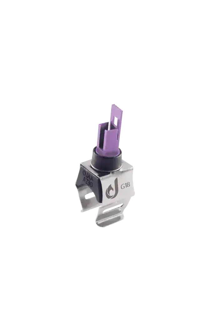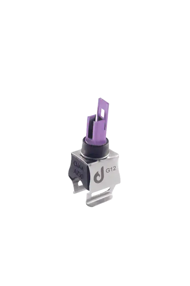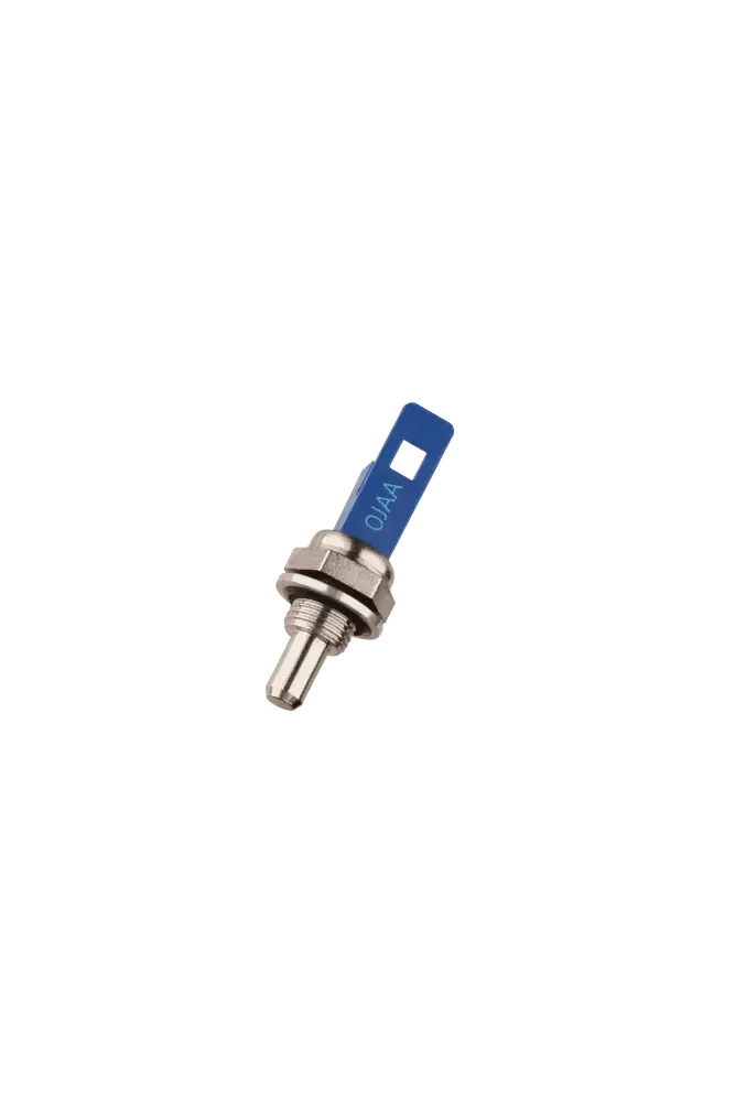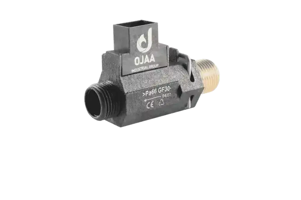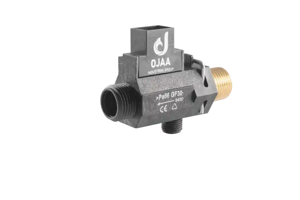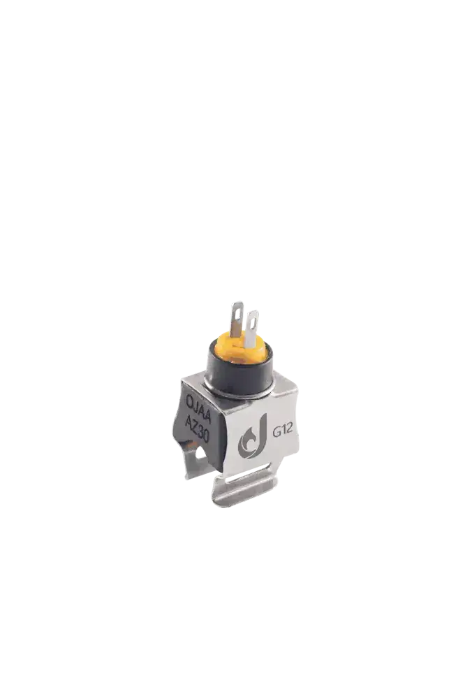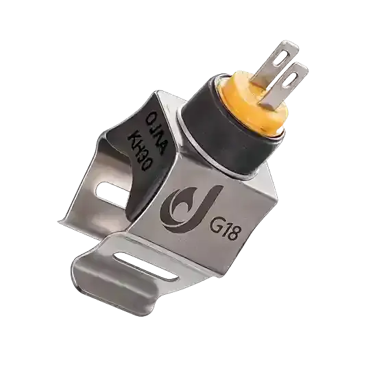
Understanding the operational principles of a boiler flow meter Hall sensor is a fundamental requirement in contemporary combi boiler diagnostics. A boiler flow meter Hall sensor is an active solid-state semiconductor transducer clipped externally onto the composite casing of a turbine flow meter, engineered to convert the physical rotation of an internal magnetic impeller into digital frequency pulses. A boiler flow meter Hall sensor requires no direct fluid contact; it detects passing magnetic poles across the polymer wall, transmitting a square-wave frequency signal to the printed circuit board to regulate gas burner firing. During heating maintenance calls, technicians frequently misjudge hot-water failure, replacing the entire hydraulic flow meter housing when the fault resides exclusively within the external electronic Hall sensor. Because the Hall sensor is a dry component isolated from fluid waterways, field replacement takes less than two minutes without isolating building water supplies or depressurizing the boiler. This comprehensive engineering guide explores open-collector circuitry, clinical failure modes, bench testing steps, and replacement standards.
Physical Principles of Hall-Effect Sensing in Fluid Transducers
The operating mechanics of a flow meter Hall sensor rely on the physical Hall effect, wherein charge carriers traversing an active semiconductor strip experience transverse deflection in the presence of an orthogonal magnetic field, creating a measurable potential difference known as the Hall voltage. Within the combi flow meter, this sensing element is hermetically sealed inside an epoxy resin package. As domestic hot-water draw spins the internal turbine, miniature permanent neodymium magnets embedded in the impeller blades sweep past the Hall integrated circuit. Each magnetic pass toggles an internal NPN bipolar junction transistor. Configured in an open-collector topology alongside a pull-up resistor on the main boiler control board, the sensor switches the output line between 5V DC and 0V DC. The resulting square-wave pulse train exhibits a frequency directly proportional to turbine rotational velocity, allowing the microprocessor to compute real-time flow in liters per minute. In quality control assessments at OJAA Industrial Group production facilities in Abbasabad Industrial Estate, magnetic switching sensitivity and noise immunity against ignition electrode electromagnetic interference are rigorously validated across production batches.
Pinout Architecture and Wiring Conventions
Standard domestic boiler Hall-effect flow sensors interface with the appliance wiring loom through a dedicated 3-wire harness: Positive Excitation Rail (VCC): Receives a regulated direct-current supply—strictly 5. 0V DC—from the control board voltage regulator. Circuit Ground (GND): The common zero-volt return path completing the electrical loop back to the chassis. Pulse Signal Output (Signal Out): The conditioned digital output lead delivering square-wave frequency transitions proportional to water flow. Certain high-end sensor housings incorporate an integrated diagnostic LED that flashes in real time with turbine rotation, providing technicians with instant visual confirmation of impeller rotation and sensor excitation without diagnostic meters.
Clinical Failure Symptoms: Hall IC Breakdown vs. Mechanical Impeller Jamming
Distinguishing electronic solid-state failure from mechanical hydroblock obstruction is essential for rapid fault isolation: Boiler remains inactive despite audible turbine rotation: Sanitary water flows at high velocity and the impeller can be heard spinning freely, yet the burner fails to ignite and no tap icon illuminates; this confirms solid-state Hall IC failure. Static diagnostic LED illumination: On models featuring an integrated optical indicator, an LED that remains continuously lit or permanently dark during flow reveals internal component breakdown. Erratic hot-water temperature hunting: Micro-fractures across internal chip wire bonds cause intermittent signal dropouts during continuous draw, leading to severe burner hunting. Diagnostic fault lockouts: The boiler control board registers an absent pulse feedback error, inhibiting spark ignition.
Root Causes of Hall-Effect Transducer Breakdown
Although solid-state sensors contain no moving parts, harsh boiler operating environments induce specific failure modes: Moisture ingress from hydroblock O-ring weepage: A weeping hydraulic manifold O-ring allows water to wick into the dry sensor pocket, corroding terminal pins and damaging the Hall IC. Power rail voltage spikes: Breakdown of filter capacitors or regulator drift on an aging control board exposes the sensor to voltages exceeding 5. 5V DC, damaging the internal semiconductor junction. Excessive radiant heat exposure: Close proximity to uninsulated primary heat exchanger manifolds elevates local temperatures beyond the 85°C maximum rating, causing thermal degradation of the silicon die. Clip retention fatigue: Thermal cycling softens the polymer mounting clip, allowing the sensor to back away from the casing, reducing magnetic flux density below the actuation threshold.
Step-by-Step Safe Workshop Diagnostics
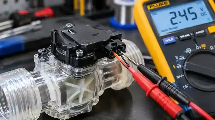
To verify Hall sensor integrity without electrical risks, execute this isolated diagnostic procedure: Step 1: Complete appliance electrical isolation Before performing maintenance, power down the combi boiler completely and disconnect the main power plug from the wall socket to guarantee full electrical safety. Step 2: Cold terminal inspection and impedance check Unplug the 3-pin harness from the sensor. Inspect the terminals for physical integrity, cleanliness, and absence of green copper oxide. With the meter set to ohms resistance under unpowered conditions, verify that terminal leads show no signs of physical shorting. Step 3: Isolated bench testing with portable DC power Slide the Hall sensor off its mounting clip (no water draining is required). On a clean workbench, connect a regulated 5. 0V DC bench supply across the VCC and GND terminals. Connect a 10 kΩ pull-up resistor between the signal output pin and the positive 5V rail. Connect a digital multimeter set to DC volts across the signal output and ground. Pass a small permanent magnet across the face of the sensor; the voltage reading should toggle cleanly between 5. 0V and near 0. 0V DC. This switching confirms full operational health of the Hall sensor. Step 4: Mechanical impeller verification With the appliance safely unpowered, open the cold-water inlet briefly to confirm audible, unimpeded turbine rotation, isolating faults to the electronic sensor rather than a jammed hydroblock.
Technician Evaluation Checklist for Component Replacement
When sourcing a replacement boiler Hall sensor, verify these engineering parameters: Clip housing geometry: Match the physical slide-on bracket profile to round or inline flow meter hydroblocks. Terminal pinout sequence: Verify the polarity alignment of 5V power, ground, and pulse signal pins to prevent reverse-voltage destruction. Environmental sealing: Ensure the replacement sensor features complete polyurethane or epoxy potting to resist ambient humidity. Impeller magnet verification: Inspect the internal turbine using an external magnetic wand to confirm magnetic poles remain active before clipping on the new sensor. O-ring inspection: Verify that hydroblock sealing O-rings are completely dry; repair weeping leaks before mounting the new electronic sensor.
Final Summary
A boiler flow meter Hall sensor provides the essential digital interface connecting hydraulic fluid movement to electronic combustion management. Its solid-state open-collector architecture ensures precision telemetry, yet moisture ingress and voltage instability require structured field diagnosis. Executing disciplined workshop bench testing, distinguishing electronic failure from mechanical impeller jamming, and utilizing dry clip-on replacement techniques restores dependable domestic hot-water comfort and prevents unnecessary hydraulic hydroblock replacements.