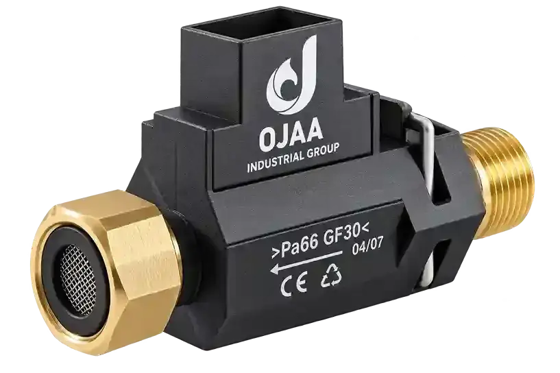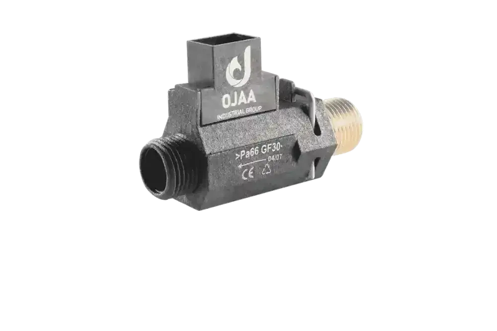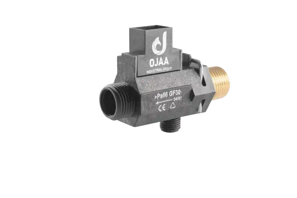
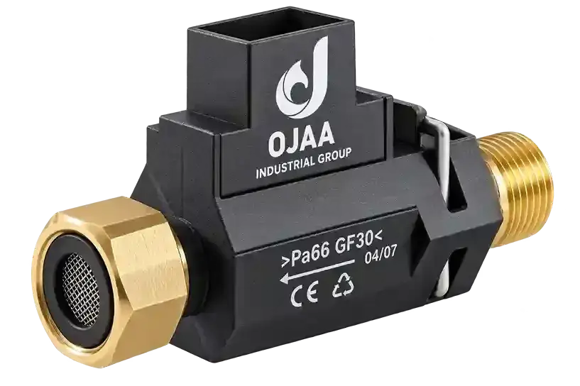
What is a boiler flow switch and what operational role does it perform during domestic hot-water cycles? A boiler flow switch is a mechanical fluid-activated sensor installed within the cold-water inlet hydroblock of a wall-hung combi boiler, engineered to detect domestic hot-water demand and initiate burner ignition. A boiler flow switch does not measure temperature or fluid volume; it functions strictly as a two-wire threshold binary contact. When sanitary flow exceeds activation parameters—typically 2. 0 to 2. 5 liters per minute—its internal contacts close, signaling the electronic control board that a hot-water fixture is open. During service interventions, technicians frequently misattribute hot-water failure to printed circuit board faults or NTC thermistor drift. In practice, over 80 percent of domestic demand failures originate from an immobilized magnetic shuttle or a degraded magnetic reed switch. This practical workshop guide details magnetic coupling mechanics, clinical failure modes, bench multimeter testing sequences, and replacement standards.
Operating Mechanics of Boiler Flow Switches
The operating mechanics of a combi boiler flow switch rely on magnetic induction between a movable internal shuttle and an external hermetically sealed reed switch. The physical assembly comprises four core elements: a composite or brass hydraulic casing, a polymer shuttle embedded with a permanent magnet, an external dry-contact reed switch, and an elastomeric seating O-ring. When a domestic tap opens, incoming water pressure lifts the magnetic shuttle upward against gravity inside its cylindrical guide. Upon reaching the upper limit of its stroke, the permanent magnet aligns with the external reed switch. The magnetic field draws the two thin ferromagnetic contact blades together, establishing a zero-volt dry contact circuit. The boiler control board registers this contact closure, drives the motorized diverter valve to the sanitary position, and fires the gas burner. When the user closes the tap, gravity or a stainless-steel return spring drops the shuttle back to its seat, breaking the circuit instantly. During manufacturing at OJAA Industrial Group production facilities located in Abbasabad Industrial Estate, flow switches are built across diverse mechanical geometries, including union-nut assemblies (OJ-FM), inline two-way bodies (OJ-F2), and integrated three-way hydroblocks (OJ-F3) engineered to match domestic heating platforms.
Technical Distinction: Flow Switches vs. Flow Meters and Water Pressure Switches
Establishing clear functional boundaries among hydraulic components prevents diagnostic errors: Distinction from flow meters: A flow switch is a two-wire binary contact indicating simple flow presence; a turbine flow meter is an active three-wire transducer measuring exact volumetric velocity via digital Hall-effect frequency pulses. Distinction from water pressure switches: A water pressure switch monitors static hydronic pressure inside the primary radiator loop in bar; a flow switch solely monitors dynamic water movement in the sanitary domestic line. Non-variable electrical signal: A flow switch generates no analog resistance curve; it is strictly an on-off interlock switching a 5V or 24V DC logic rail on the central microprocessor.
Clinical Failure Modes of Boiler Flow Switches
Flow switch failures manifest across two distinct operating anomalies in domestic heating operation: Scenario 1: Shuttle seized in the resting position or failed reed switch Domestic hot-water taps are fully open, but the boiler remains completely dormant with zero burner ignition and no tap icon on the display. Outflow water remains cold while space heating radiators continue operating normally. Tapping gently on the hydraulic hydroblock temporarily initiates ignition before dropping out, confirming mechanical shuttle friction. Scenario 2: Shuttle jammed in the elevated position or welded contacts Domestic taps are turned off, but the burner continues firing unchecked at maximum capacity. Water trapped inside the primary heat exchanger rapidly flashes to steam, causing the high-limit 105°C safety thermostat to trip on overheat. In summer mode with all taps closed, the circulation pump or burner runs continuously, overheating chassis pipework.
Root Causes of Shuttle Jamming and Electrical Breakdown
Mineral limescale encrustation: Hard water supplies deposit calcium carbonate layers across the internal cylinder, increasing frictional drag until the shuttle seizes. Debris and PTFE tape contamination: In newly commissioned plumbing, loose pipe scale, sand, or shredded thread sealant lodge between the shuttle and casing wall. Magnetic flux degradation: Continuous exposure to radiant boiler heat gradually weakens the magnetic field of the internal magnet, preventing contact closure. Arcing and welded reed contacts: Electrical spikes across control board logic circuits weld the delicate reed blades together, creating permanent continuity.
Step-by-Step Bench Diagnostics Using a Multimeter
Accurate component verification requires bench testing or testing under cold appliance conditions: Electrical safety: Disconnect mains power from the boiler completely before accessing internal hydroblocks. Terminal disconnection: Slip the two female spade terminals off the flow switch reed contacts. Never test continuity while leads remain connected to the live board. Meter configuration: Set the digital multimeter to the continuity buzzer mode or lowest ohms resistance range (200 Ω). Static baseline test (zero flow): Connect meter test leads across the two switch pins. With no water flowing, the circuit must remain completely open; no tone must sound, and the meter should display an over-range (OL) reading. Dynamic flow simulation: Open a domestic hot-water tap, or on the test bench, direct clean water or gentle air pressure through the inlet to lift the shuttle. Contact closure evaluation: As the shuttle rises, the contacts must close instantly; the continuity buzzer must sound a steady tone, with resistance reading below 1. 0 ohm. Reset verification: Cease flow; the buzzer must silence immediately as the shuttle drops. If continuity remains permanently open or permanently shorted in both states, the flow switch assembly requires cleaning, reed replacement, or full component renewal.
Technician Evaluation Checklist for Component Replacement
When sourcing a replacement boiler flow switch, verify these technical parameters: Body mechanical geometry: Confirm union-nut threads, inline two-way push-fit ports, or three-way manifold architectures. Retention mechanism: Match securing spring clips, brass union collars, or threaded studs. Vertical mounting orientation: Ensure the replacement is positioned vertically; flow switch shuttles rely on gravity for reset, and tilted installations cause chronic sticking. Inlet filter screen verification: Ensure an intact fine mesh strainer is fitted upstream to protect the shuttle from pipeline grit. Elastomeric seal replacement: Always install brand-new WRAS-compliant EPDM O-rings lubricated with pure silicone grease to eliminate weeping leaks.
Final Summary
A boiler flow switch is the primary ignition trigger for domestic hot-water delivery. Its magnetic shuttle and reed switch mechanism provides reliable binary control, but performance depends on free mechanical travel and clean hydraulic passages. Executing disciplined multimeter continuity testing, checking shuttle mobility, and matching hydraulic body architectures prevents unnecessary control board replacements and guarantees dependable domestic hot-water operation.