The beating heart of the combustion system in any wall-hung boiler is the boiler gas valve. This highly sensitive electromechanical component receives direct commands from the printed circuit board (PCB) to precisely regulate the volume of gas entering the burner, matching the building's exact thermal demands. When this part fails, or its electrical solenoid coils burn out, it directly results in ignition failures, explosive lighting, or severe fluctuations in domestic hot water temperatures.
What is a Boiler Gas Valve and How Does it Function?
A boiler gas valve is a monolithic aluminum assembly containing dual sequential solenoid coils and a modulating flow regulator, installed between the gas supply pipe and the burner manifold. Its primary mandate is the safe isolation of fuel and dynamic flame modulation. To guarantee absolute safety, this component is structurally designed with two fail-safe mechanisms. Safety Solenoids (EV1 and EV2): These two coils operate simultaneously when supplied with 230V mains power (or DC in some variants) to open the primary gas pathway. If either coil fails, the entire valve remains shut. Boiler Modulation Valve (Modulator): A smaller, low-voltage DC coil that adjusts the physical height of the flame in real-time based on PCB signals, ensuring the hot water temperature remains perfectly stable. Mechanical Adjustment Points: The valve body features specific brass adjustment screws for setting the minimum and maximum burner pressures, which technicians calibrate using a digital manometer.
Diagnosing a Boiler Gas Valve Failure and Ignition Lockouts
Identifying a boiler gas valve failure requires distinguishing between electrical faults (burnt coils) and mechanical faults (seized internal diaphragms). The flame rectification electrode immediately reports a lack of combustion to the PCB, which safely locks out the appliance. The most prominent symptoms of a failing gas control assembly include: Sparking but No Ignition: If the fan runs and the ignition electrodes spark, but no flame appears, the safety solenoid coils have likely burnt out, keeping the gas pathway completely sealed. Fluctuating Water Temperatures: A failure in the boiler modulation valve prevents the PCB from turning the flame up or down. The boiler runs at maximum capacity, overheats, and shuts down repeatedly, causing hot and cold temperature spikes. Explosive Ignition: Incorrect mechanical pressure settings or a sticking internal valve mechanism allows unburnt gas to pool in the combustion chamber, resulting in a loud bang when the spark finally ignites it.
How to Perform Testing on Boiler Gas Valve Coils
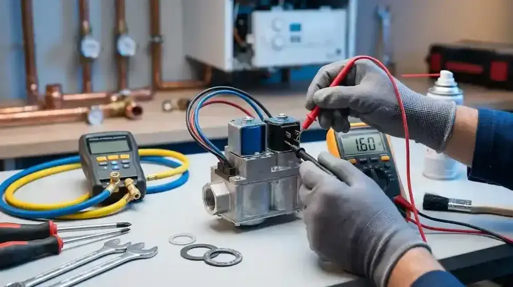
Testing boiler gas valve solenoids electrically is the safest workshop method to verify the integrity of the component. Unauthorized mechanical dismantling or opening the sealed aluminum body of a gas valve is highly dangerous and strictly prohibited. To safely test the solenoid coils, adhere to the following diagnostic steps: Electrical Isolation: Disconnect the boiler from the mains power and unplug the electrical wiring harness connected to the gas valve to expose the metallic pins. Multimeter Ohmic Resistance: Set a digital multimeter to the resistance (Ohms) setting and place the probes across the pins of the safety solenoids. Interpreting the Values: Standard safety coils (like those on SIT 845 valves) usually exhibit a resistance between 800 and 6000 Ohms. A reading of zero signifies a short circuit, while infinity indicates an open (burnt-out) coil, necessitating replacement.
Safe Checklist for Pressure Adjustment and Part Replacement
Any gas valve solenoid coils replacement or mechanical gas pressure adjustment must be performed exclusively by certified gas-safe engineers utilizing a calibrated digital differential manometer. When servicing or replacing this component, the following protocols are critical: Checking Standing Pressure: Before condemning the valve, technicians must verify that the incoming mains gas supply pressure is adequate (typically 20mbar for Natural Gas). Replacing Sealing Washers: If the valve is removed, all inlet and outlet Klingersil or rubber gas washers must be discarded and replaced with brand-new OEM equivalents. Mandatory Leak Testing: After installing the new component, all threaded and flanged gas joints must be rigorously tested using an electronic gas sniffer or approved leak detection fluid to guarantee a hermetic seal.
Final Summary
The boiler gas valve is the most critical safety barrier in the combustion system, responsible for both fail-safe fuel isolation and active flame modulation. Faults such as explosive ignition, fluctuating water temperatures, or sparking without a flame strongly point to a boiler gas valve failure or burnt solenoids. Technicians must utilize a multimeter for testing boiler gas valve coils and a calibrated manometer for any pressure adjustments. Remember, gas-carrying components must never be modified or repaired using substandard practices.