The initiation and continuous operation of the burner in any wall-hung gas boiler rely heavily on the flawless performance of the ignition and flame monitoring components. Positioned in the heart of the combustion chamber, these parts act as the electronic eyes and hands of the main printed circuit board (PCB). Degradation, oxidation, or incorrect spacing of these metallic rods immediately results in safety lockouts. Mastering the testing and calibration of these electrodes is one of the most critical skills for resolving persistent ignition failures in the workshop.
What Are Boiler Ignition and Flame Sensing Electrodes?
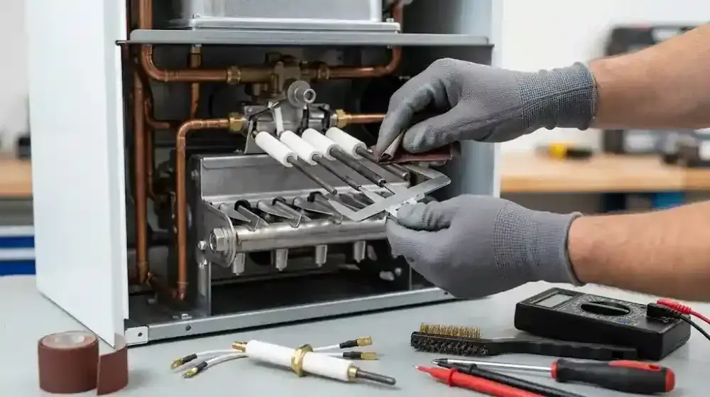
Boiler ignition and flame sensing electrodes are specialized rods manufactured from heat-resistant alloys (such as Kanthal), encased in cylindrical ceramic insulators, and mounted directly above the burner assembly. Depending on the boiler model, this system can be designed as a single dual-purpose electrode or as a multi-electrode configuration. The Spark Ignitor: The spark generator transformer steps up the 230V mains to an extremely high voltage (approximately 10, 000 to 15, 000 volts). This voltage discharges between the electrode tip and the grounded burner chassis, creating the electrical arc necessary to ignite the gas. Flame Rectification (Sensor): Once the flame is established, the gas molecules ionize and become electrically conductive. The flame sensor passes a tiny micro-ampere current through the flame to the earth ground, confirming the presence of combustion to the PCB. Component Layout: In multi-electrode systems, the sparking electrodes are usually positioned centrally or to the left of the burner, while the flame sensing rod is positioned to the right to monitor the spread of the flame.
Causes of a Boiler Not Sparking and Ignition Lockouts
One of the most frequent faults technicians face is the appliance locking out with an ignition failure code (e. g. , E01). Investigating a boiler not sparking requires a methodical check of the high-voltage electrical pathway from the PCB to the combustion chamber. A failure in this section to initiate or confirm a flame is caused by several specific issues. High-Voltage Cable Faults: If the silicone-insulated cable connecting the transformer to the electrode is damaged or degraded, the high voltage arcs directly to the boiler chassis (shorting out) before it can reach the electrode tip, resulting in no spark at the burner. Cracked Ceramic Insulators: Hairline cracks in the electrode's ceramic body allow the high voltage to track through the fissure and discharge into the mounting plate rather than jumping the gap to the burner. Severe Oxidation: A thick layer of carbon and oxidized metal on the electrode tips acts as a perfect insulator, preventing the spark from jumping the gap or stopping the micro-ampere flame rectification current from flowing.
The Importance of Ignition Electrode Gap and Explosive Lighting
If the boiler sparks but ignites with a loud, frightening bang (explosive ignition), the core issue is the pooling of unburnt gas prior to ignition. In this scenario, calibrating the ignition electrode gap is the definitive solution. Adhering to strict factory spacing standards is mandatory to prevent combustion hazards. Standard Spark Gap: The distance between the tip of the ignition electrode and the surface of the burner blades must be strictly maintained between 3mm and 5mm. A wider gap weakens the arc, while a narrower gap fails to expose the spark adequately to the gas-air mixture. Flame Sensor Positioning: The ionization rod must be positioned so that at least 8mm to 10mm of its metallic tip is fully engulfed in the flame to guarantee a stable rectification current. Avoid Cold Bending: Never apply excessive force to bend an electrode while it is completely cold, as the brittle ceramic base will instantly snap.
Safe Checklist for Boiler Flame Sensor Cleaning and Testing
If the boiler successfully ignites but shuts down entirely after 3 to 5 seconds, the PCB has failed to detect the flame. At this stage, boiler flame sensor cleaning and ionization testing are the only viable solutions. To perform a professional and safe service, execute the following steps: Electrical Isolation: Due to the lethal high voltages generated by the spark transformer, completely unplug the appliance from the mains power before opening the sealed combustion chamber. Cleaning with Emery Cloth: Using a very fine grade of emery cloth or steel wool, gently rub the metallic tips of the electrodes to remove all carbon soot and oxidation until the bare, shiny metal is exposed. Micro-Ampere Testing: Set a digital multimeter to the micro-amps (μA) function. Connect it in series with the flame sensor wire while the burner is running to verify the current (a healthy reading is typically between 1. 0 and 5. 0 μA). Verifying the Earth Connection: The flame rectification process relies entirely on a solid earth ground. If the boiler's earth connection is loose or missing, the flame sensor will completely fail to operate.
Final Summary
Boiler ignition and flame sensing electrodes are the frontline components of the combustion safety system. Issues such as a boiler not sparking, explosive ignition, or the burner dropping out after a few seconds are directly linked to dirty sensors, cracked ceramics, or an incorrect ignition electrode gap. Diagnosing these faults requires a thorough inspection of the high-voltage leads and testing boiler electrodes for micro-ampere continuity. Always prioritize meticulous boiler flame sensor cleaning and verifying the building's earth connection before condemning the expensive main control board.