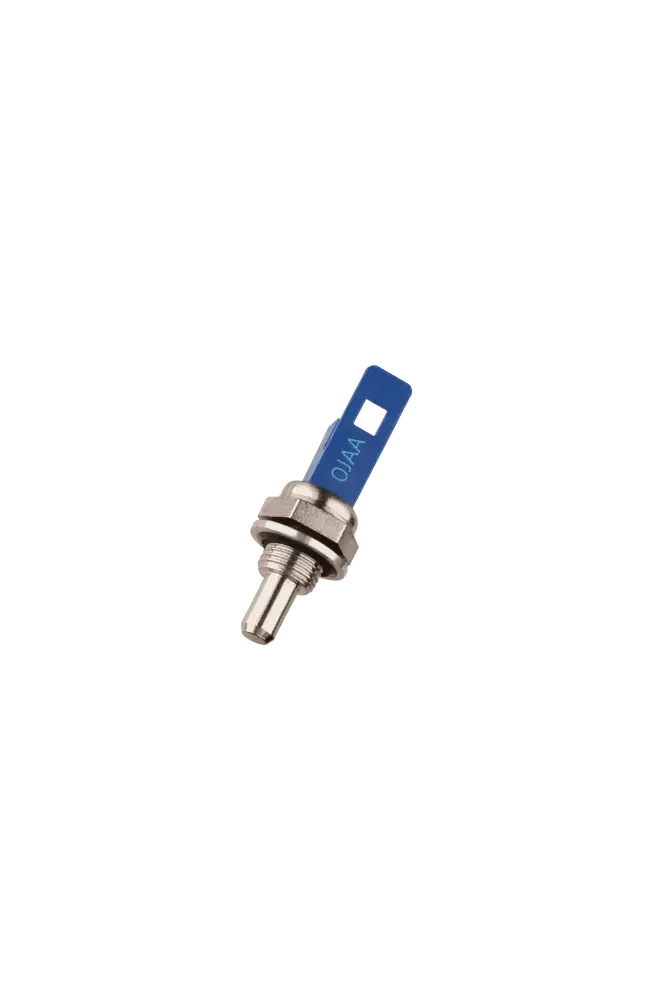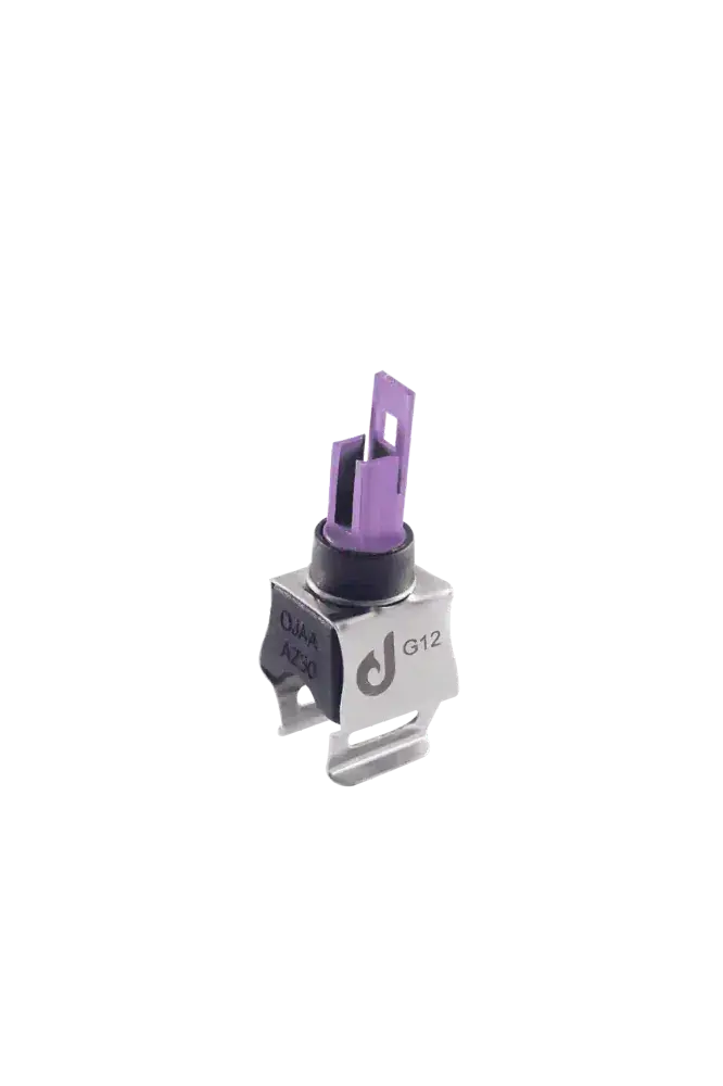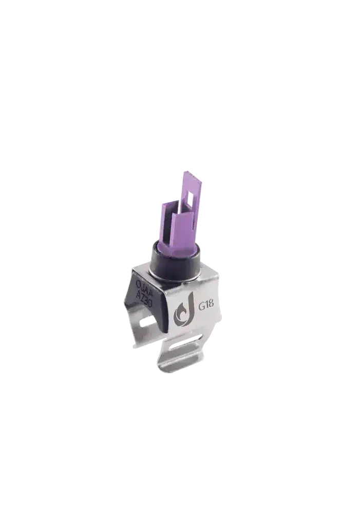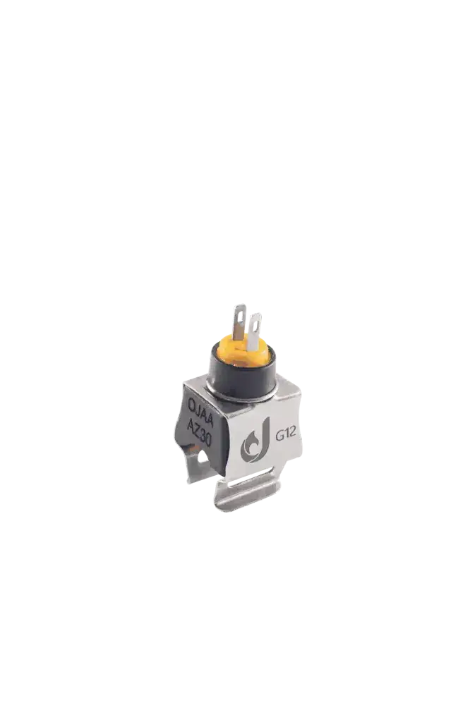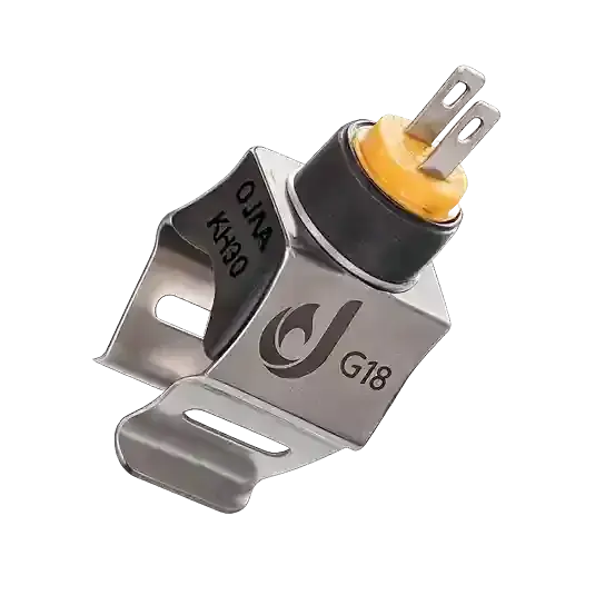
Boiler NTC resistance is the primary electronic variable the control board relies upon to modulate the burner flame accurately. Temperature sensors in wall-hung boilers are not mechanical switches; they are precision semiconductors with strict tolerances governed by logarithmic curves. Installing a sensor with an incorrect nominal resistance severely disrupts the board's calibration, leading to repeated thermal errors.
What is Boiler NTC Resistance and How Does It Function?
Boiler NTC (Negative Temperature Coefficient) resistance refers to a semiconductor component whose electrical resistance drops inversely as the water temperature increases. The control board calculates the precise fluid temperature by monitoring this resistance drop. The behavior of these semiconductors is non-linear and operates according to the Steinhart-Hart equation and a specific B-value (typically 3435K to 3950K). To understand this function, consider the following points: At Standard Room Temperature: The resistance sits at its highest nominal standard, signaling to the board that the circuit is cold. During Burner Ignition: As the brass sheath absorbs heat, the sensor's resistance plummets, triggering the board to reduce flame height. Safety Logic: If the resistance becomes infinite (due to a broken cable), the board immediately logs a sensor error and extinguishes the flame.
What is the Difference Between 10K and 50K NTC Sensors?
The strict difference between 10K and 50K boiler NTC sensors lies entirely in their base resistance at the standard reference temperature of 25°C. A 10K sensor provides exactly 10 kilo-ohms at 25°C, while a 50K sensor exhibits 50 kilo-ohms under identical conditions. These two components are completely non-interchangeable because the voltage divider circuit on the electronic board is calibrated for only one specific curve. 10K Sensor: This is the dominant standard used in over 90% of wall-hung combi boilers, offering exceptionally high resolution at lower temperature brackets. 50K Sensor: Utilized in specific imported control boards or certain condensing boilers, optimized for precision in significantly higher temperature ranges. Calibration Error: Installing a 10K sensor on a board designed for 50K causes the processor to falsely assume the water is boiling, instantly locking out the appliance.
Boiler NTC Sensor Resistance Chart (10K Calibration)
The boiler NTC sensor resistance chart is a standard technical reference used by technicians to verify that the component has not drifted from its thermal curve. This chart specifies the semiconductor's nominal resistance across various temperatures. The following values are valid for standard 10K sensors with a 1% tolerance (±1%) commonly found in wall-hung boilers: Resistance at 0°C: Approximately 27 to 32 kilo-ohms. Resistance at 25°C: Exactly 10 kilo-ohms (Factory reference point). Resistance at 40°C: Approximately 5. 3 kilo-ohms (Common domestic hot water temperature). Resistance at 60°C: Approximately 3 kilo-ohms (Standard central heating flow temperature). Resistance at 80°C: Approximately 1. 5 kilo-ohms (Approaching the safety thermostat threshold).
Safe Multimeter Testing Method for NTC Resistance
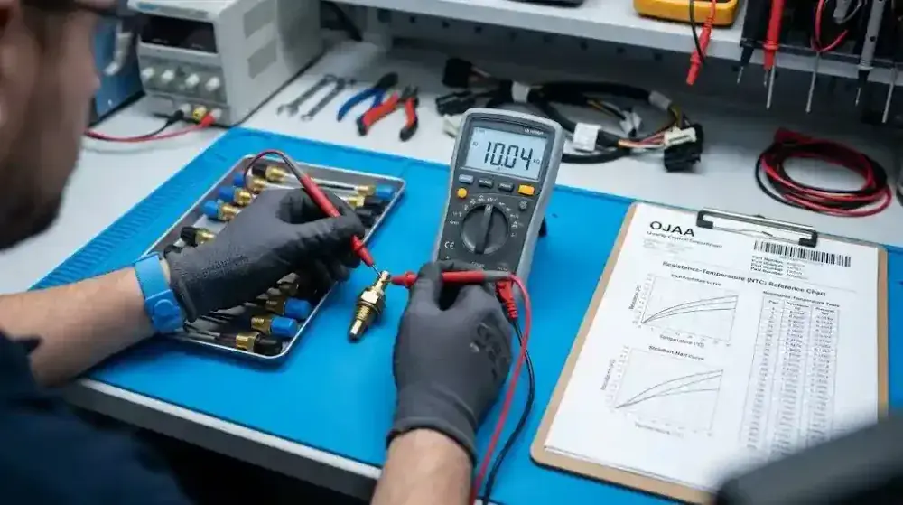
The safe testing of boiler NTC resistance must be conducted strictly via a cold ohmic test at ambient room temperature. Any testing under live mains voltage or applying artificial heat is highly dangerous and strictly prohibited. To evaluate the health of the semiconductor and confirm the absence of thermal curve deviation, adhere to these guidelines: Complete Electrical Isolation: Fully unplug the boiler from the mains and disconnect the sensor socket to prevent the board's voltage from interfering with the multimeter. Ambient Temperature Measurement: Set the digital multimeter to the 20 kΩ range; at an ambient workshop temperature of approximately 25°C, the display should read near 10 kΩ. Sheath Continuity Check: Connect one probe to the sensor pin and the other to the metal sheath; if any resistance value appears, the internal insulation has ruptured and the part must be discarded.
Final Summary
Boiler NTC resistance is the most crucial electronic parameter ensuring safe operation and accurate flame modulation in a combi boiler. Mastering the standard temperature chart and understanding the structural differences between 10K and 50K sensors prevents the unnecessary replacement of parts and misdiagnosis. Always perform health checks using cold ohmic measurements at room temperature, and ensure replacement parts match the exact part number and nominal resistance.