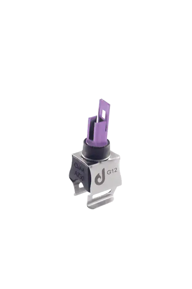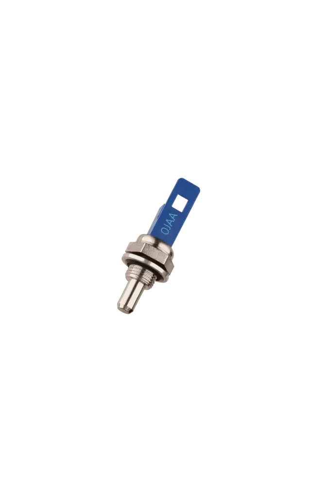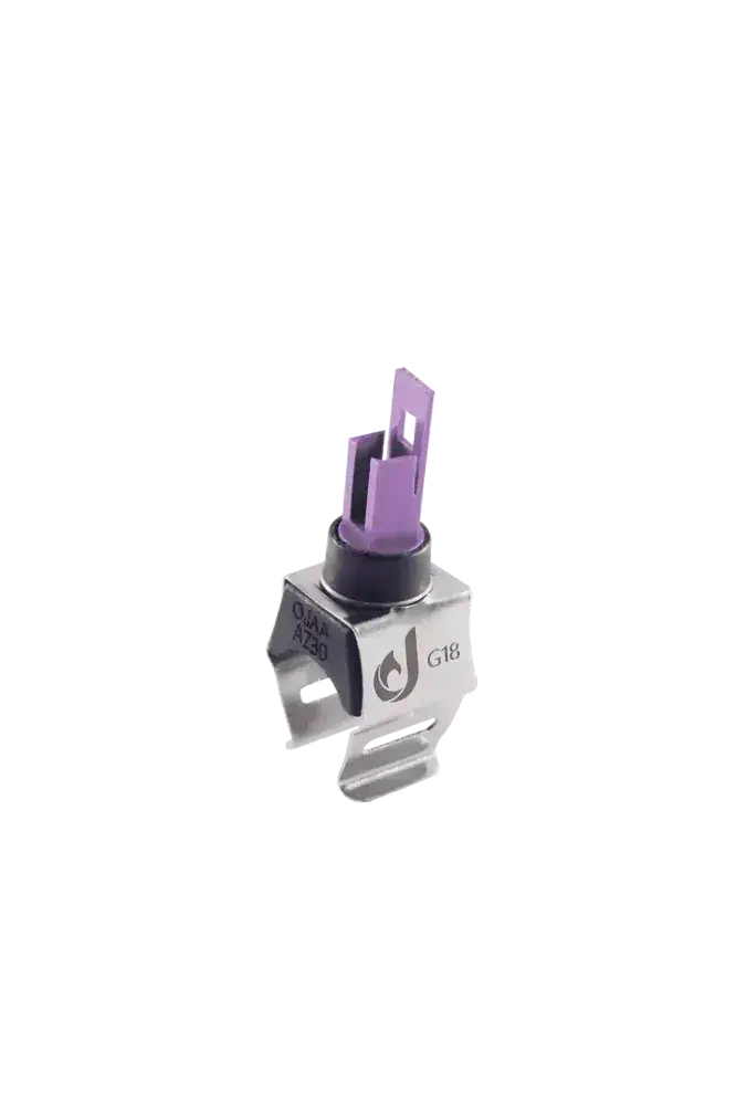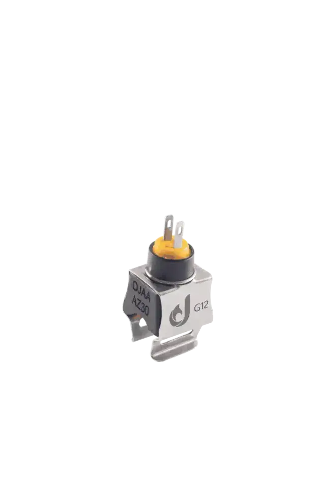
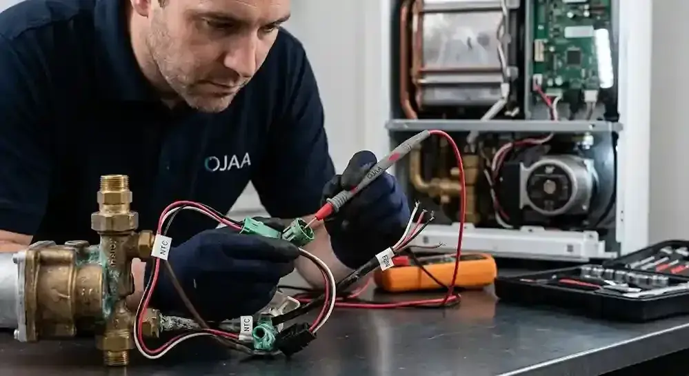
The boiler NTC socket and flow meter wire are among the most critical signal transmission components within the appliance's electronic system. Frequently, technicians replace sensors upon seeing an error code, whereas the actual fault lies in severed wire strands, cold solder joints, or oxidized connector pins. Ensuring the integrity of the wiring harness and sockets is a mandatory prerequisite for any diagnostic procedure.
What is a Boiler NTC Socket and Why Does It Oxidize?
A boiler NTC socket is a plastic connector (usually made of heat-resistant polyamide) that establishes the electrical connection between the temperature thermistor and the main wiring harness. Continuous exposure to high heat and moisture leaks causes the metal pins to oxidize. Parasitic resistance at the socket connection causes the control board to misinterpret water temperature data. The primary causes of socket failure include: Water Leaks: Water dripping from worn O-rings onto the socket leads to severe corrosion and sulfation of the brass terminals. Excessive Heat: Operating in close proximity to the primary heat exchanger without thermal insulation causes the plastic to dry out and turn brittle. Dynamic Vibration: Constant vibrations from the pump and fan gradually loosen the mechanical retaining clip, causing intermittent electrical noise.
Symptoms of Wire Faults in the Flow Meter Harness
The boiler flow meter wire is typically a three-core cable that transmits supply voltage, ground, and sensor pulse outputs. A break in any of these strands prevents the board from detecting domestic hot water flow. When a break occurs in this pathway, the boiler remains entirely unresponsive to the opening of a hot water tap. Common symptoms include: Burner Ignition Failure: Despite the turbine spinning, the pulse signal never reaches the control board, leaving the appliance in standby mode. Erratic Flame Cycling: A cold solder joint at the board's connector or a partially severed wire causes fluctuating signals, making the burner ignite and extinguish repeatedly. False Sensor Error Codes: Voltage drops across a degraded wire path prompt the control board to display false flow meter or Hall sensor faults.
How to Test Wiring and Sockets with a Multimeter
To verify cable health, technicians must perform a cold continuity test using a digital multimeter. This test determines whether the electrical pathway from the sensor socket directly to the board's connector is fully intact. This procedure must strictly be performed with the boiler completely disconnected from the mains power to prevent destroying the processor. The steps are as follows: Unplug the boiler from the electrical outlet and disconnect the sockets from both the sensor and the control board. Set the digital multimeter to the continuity (buzzer or diode) testing mode. Place one probe on the sensor-side socket pin and the other probe on the corresponding pin at the board-side connector. Hearing a continuous beep (indicating near-zero resistance) confirms that the wire strand is perfectly healthy. Hearing no beep or seeing fluctuating resistance values proves there is an open circuit or loose connection, dictating a harness replacement.
Checklist for Selecting Replacement Sockets and Wires
Selecting high-quality cables and connectors is absolutely vital to prevent recurring electrical faults. Parameter One (Body Material): The socket must be molded from heat-resistant plastics (such as PA66) to ensure it does not melt near hot hydraulic pipes. Parameter Two (Pin Quality): It is essential to use brass pins with tin or silver plating to prevent oxidation in the humid environment of the boiler. Parameter Three (Wire Gauge): The thickness of the copper strands must perfectly match the original factory AWG standards to prevent signal voltage drops. Parameter Four (Mechanical Lock): The replacement connector must feature a robust locking clip so it does not vibrate loose from the sensor over time.
Final Summary
The integrity of the boiler NTC socket and flow meter wire is just as critical as the sensors themselves. Many unnecessary component replacement costs can be avoided through simple visual inspections and standard continuity tests. During routine servicing, always inspect communication pins for sulfation and replace any brittle or melted sockets with standard, heat-resistant equivalents.