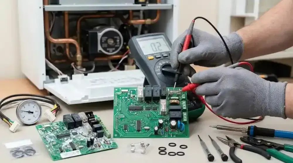
The central processing brain and absolute commander of any modern smart boiler is the boiler PCB (Printed Circuit Board). This highly complex circuit analyzes incoming signals from safety sensors and transmits operational commands to heavy-duty actuators like the gas valve, circulation pump, and exhaust fan. When this processing unit fails, the entire hydraulic and combustion system is paralyzed. Understanding the architecture of this board and distinguishing between superficial faults (like a blown glass fuse) and terminal damage (like a burnt microprocessor) helps technicians avoid premature and costly replacements.
What is a Boiler PCB and What Are Its Core Components?
A boiler PCB is a multi-layered printed circuit board housed within an insulated plastic casing behind the front drop-down fascia. Its primary duties include safety management, dynamic flame modulation, and precise water temperature regulation. This main controller consists of several highly sensitive electronic components designed to manage varying voltages. Switched-Mode Power Supply (SMPS): Converts the incoming 230V alternating current (AC) into low-voltage direct current (DC)—typically 5V, 12V, and 24V—required to power the sensors and microchips. Command Relays: These are small black or transparent electromagnetic switches. Their role is to safely switch the high 230V power to heavy-load components like the fan motor, pump stator, and gas valve solenoids. Microcontroller (MCU): The central integrated circuit (IC) where the manufacturer's operational software is flashed. It executes all safety logic algorithms, such as triggering a lockout if ignition fails. Thermal and Glass Fuses: Protective sacrificial components installed on the main power input pathways. They blow instantly during severe electrical surges to protect the more expensive downstream microchips.
Diagnosing a Boiler Not Turning On and Blown Fuses
One of the most alarming scenarios for a user is a completely dead appliance (blank display and no indicator lights). In these instances, the reason for the boiler not turning on usually points to the PCB's power supply sector or a severe short circuit in a connected peripheral. A glass fuse that repeatedly blows indicates a critical underlying fault that must be identified. Mains Power Surges: A sudden spike in the building's electrical grid triggers the PCB's varistor. The varistor creates a deliberate short circuit to blow the 2-amp glass fuse, thereby protecting the rest of the board. 230V Component Short Circuits: If the gas valve coils, pump stator, or fan windings suffer from water ingress or burnt insulation, they draw massive amperage the moment the PCB commands them to run, instantly blowing the main fuse. Wiring Harness Chafing: If the internal wiring harnesses rub against the sharp metal chassis of the combustion chamber, the exposed copper wires short the live feed directly to earth, shutting down the main board.
The Dangers of Water Leaks and PCB Oxidation
Moisture is the ultimate enemy of electronic circuits. Because the main control board is positioned directly beneath the hydraulic components (like the flow switch, pump, and filling loop), it is highly vulnerable to dripping water. Water damage to the main controller produces destructive and often irreversible effects. Water Conductivity and Shorting: Even a few drops of system water bridging the pins of an IC or transistor will create an unintended electrical path, instantly frying the microprocessor. Copper Track Oxidation: If the internal boiler environment is highly humid, the exposed copper tracks and component pins develop a green or white powdery oxidation (sulfation). This alters the circuit's resistance, causing erratic phantom errors. Relay Contamination: Moisture penetrating the command relays causes the internal contacts to arc and carbonize. Consequently, the boiler may throw a fan or pump error code, even though those physical components are perfectly healthy.
Workshop Checklist for PCB Diagnostics and Testing
Heating and plumbing technicians are generally not expected to perform component-level soldering repairs on PCBs (this requires specialist electronics training). However, they are entirely responsible for accurately diagnosing PCB failures and isolating them from mechanical faults. To safely evaluate the health of the main board, follow these strict procedures: Absolute Electrical Isolation: Before opening the plastic control housing, physically unplug the appliance from the wall socket. The risk of lethal 230V electric shock around the power supply sector is extreme. Visual Inspection: Look closely for physical evidence of failure: blackened burn marks around resistors, bulging or leaking electrolytic capacitors, blown ICs, or white water-staining across the green solder mask. Continuity Testing the Fuse: Set a digital multimeter to the continuity (buzzer) function and probe both ends of the glass fuse. If the multimeter remains silent, the fuse has blown. Remote Sensor Testing: To verify the integrity of the wiring harness, test the resistance of the NTC thermistors from the terminal block plug that connects directly into the PCB, rather than at the sensor itself.
Final Summary
The boiler PCB is the operational core managing heat, hydraulics, and absolute safety. Issues such as a completely blank display, persistently blown protective fuses, and erratic phantom error codes directly point to a failing control board or a short circuit in a peripheral component (like a pump or fan). Diagnosing a boiler not turning on requires meticulous inspection of the wiring harness and testing the peripheral parts. To protect this expensive processing unit from oxidation, always repair minor hydraulic drips immediately, and if replacement is necessary, utilize only genuine manufacturer-approved control boards.