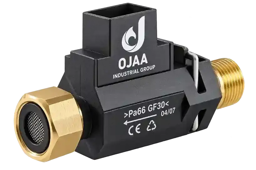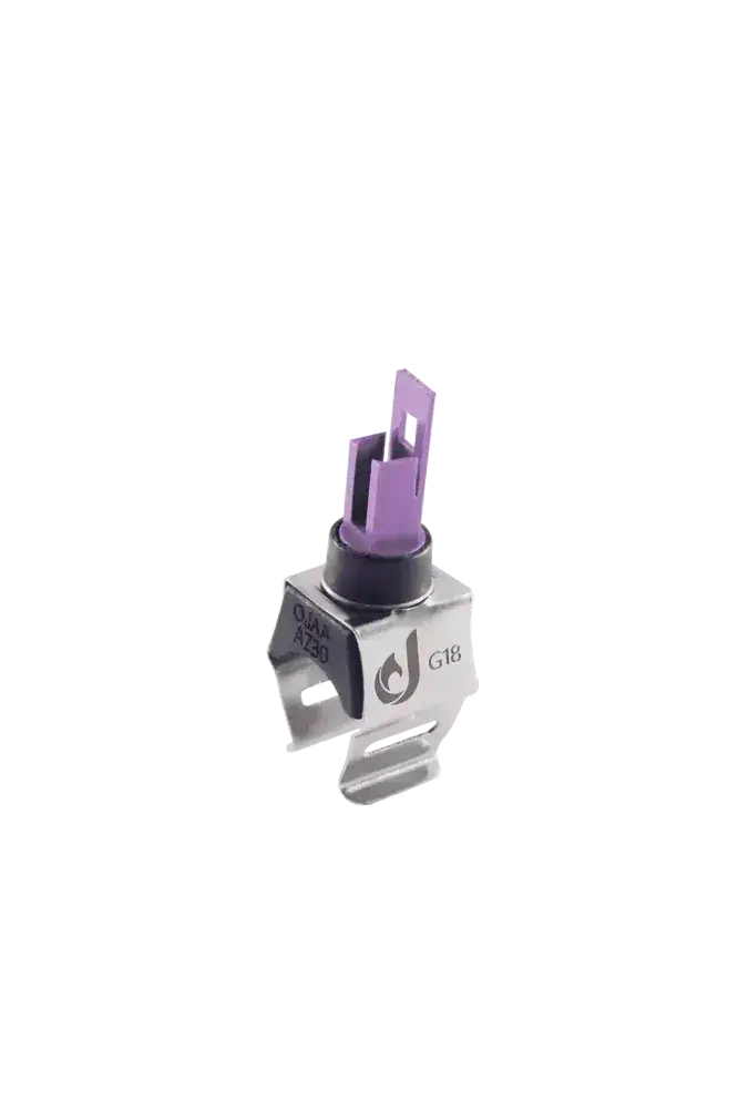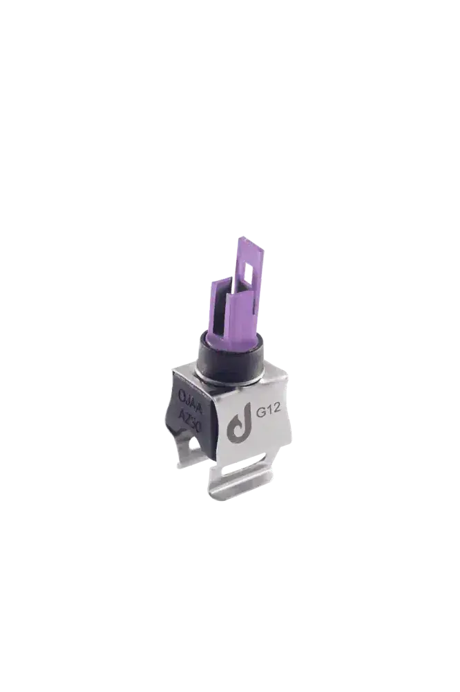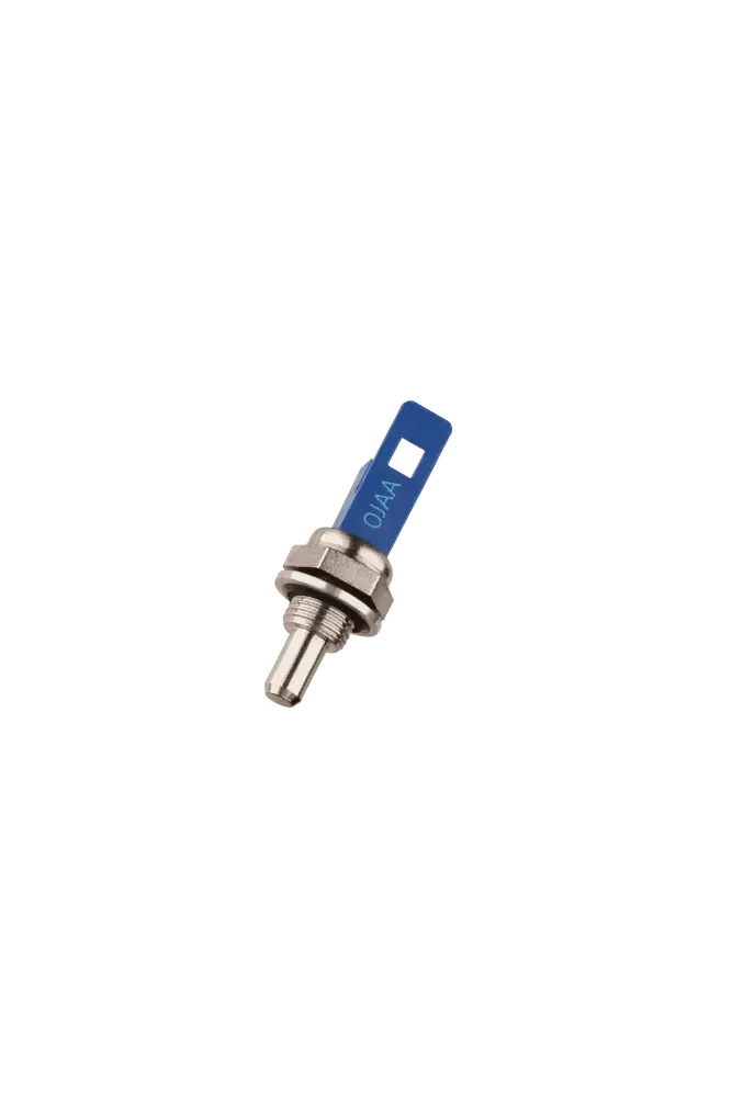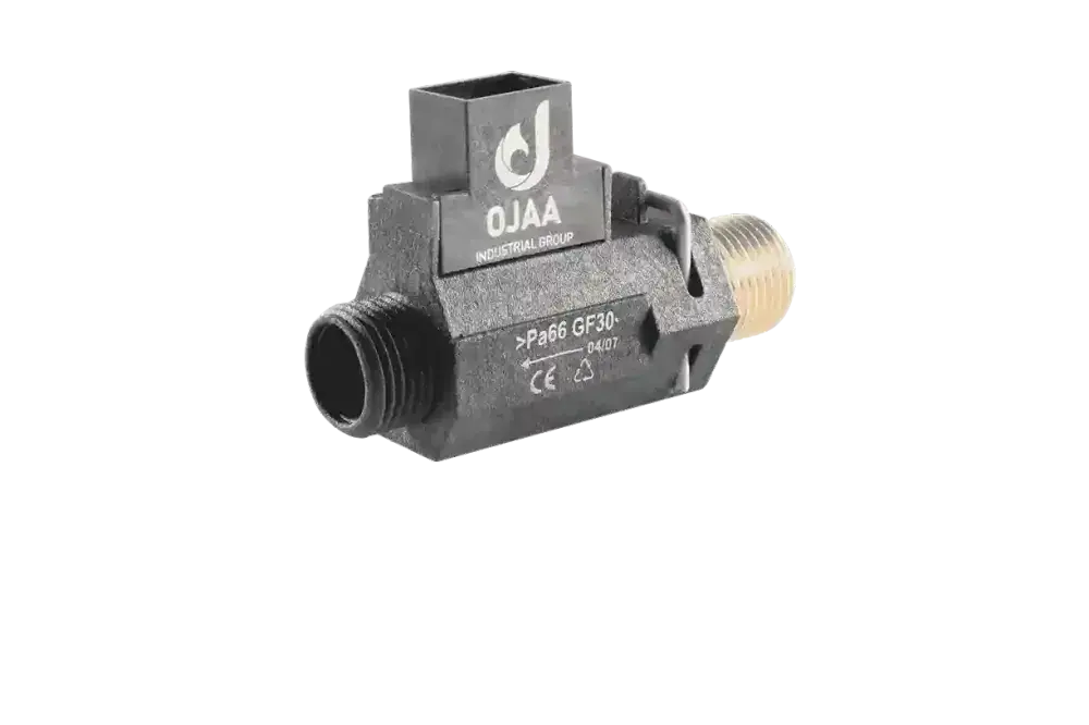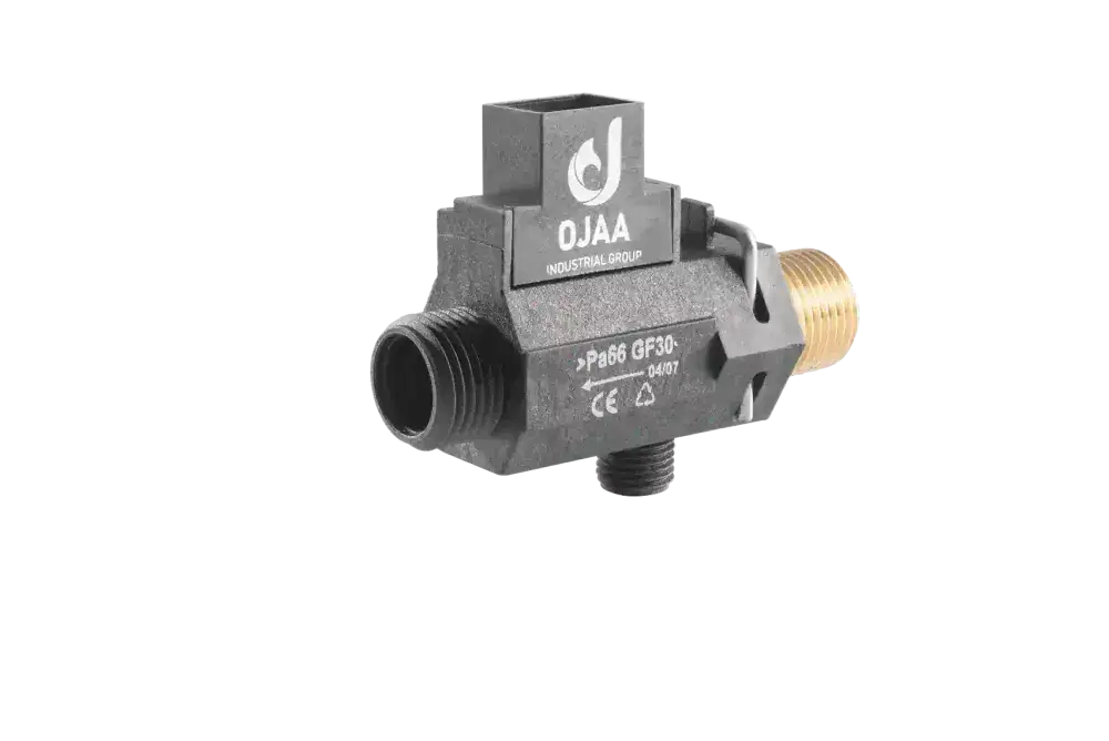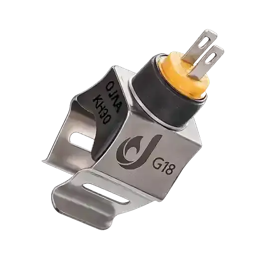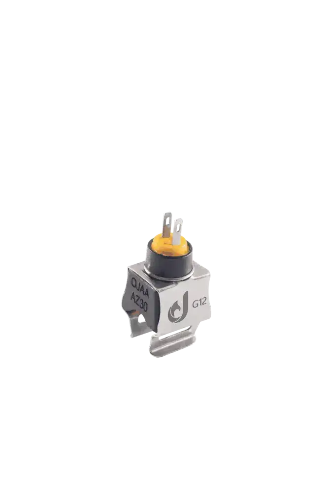
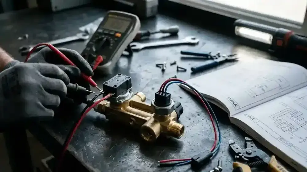
The difference between a boiler pressure switch and a pressure sensor is one of the most common points of confusion among junior technicians. Although both components interact with the central heating water and monitor hydraulic pressure, their internal architecture, output signals, and communication logic with the control board are entirely different. Failing to distinguish between them leads to incorrect part purchases, inability to clear pressure error codes, and severe damage to the electronic circuit.
What is a Boiler Water Pressure Switch and How Does It Work?
A water pressure switch is a simple electro-mechanical device with a binary on/off output that solely confirms the presence of minimum water pressure in the system. Until the water pressure reaches the factory threshold (usually 0. 5 bar), its internal contacts remain open. This component functions strictly as a basic safety interlock and does not transmit any precise pressure values to the control board. Internal Structure: Consists of a rubber diaphragm, a calibrated tension spring, and a two-wire microswitch. Signal Output: Simply closes or opens an electrical circuit (continuity). Testing Method: Verified using a digital multimeter set to the continuity (buzzer) mode while the appliance is powered off.
What is a Pressure Sensor (Transducer) and How Does It Differ?
A water pressure sensor (transducer) is a highly sensitive, three-wire electronic component that measures the instantaneous circuit pressure and transmits it to the main processor as a continuous, analog voltage signal. Unlike the simple on/off switch, the transducer allows the main control board to display the exact bar pressure numerically on the boiler's LCD screen. Operating Mechanism: Utilizes piezoresistive sensing elements whose electrical resistance—and thus output voltage—changes proportionally to the applied physical pressure. Signal Output: Sends a variable analog signal (typically ranging from 0. 5 to 3. 5 Volts DC) to the main board. Power Supply: Requires a stable 5V DC reference voltage from the control board to operate correctly.
Comparison and Differences Between Pressure Switches and Sensors
The primary difference between these two components lies in their data transmission capabilities; a pressure switch is a basic safety cutoff, whereas a pressure sensor is a precision hydraulic monitoring instrument. During appliance troubleshooting, noting these structural and functional differences prevents costly misdiagnoses. Number of Wires: Pressure switches are two-wire components, whereas pressure sensors (transducers) always feature a three-wire configuration (supply, ground, and signal). User Display: Boilers utilizing a pressure switch typically feature an analog mechanical pressure gauge on the fascia; boilers with sensors display the bar pressure digitally. Precision Control: A transducer allows the board to preemptively shut down the burner at high pressures (e. g. , near 3 bar) before the mechanical safety relief valve lifts. A standard switch cannot control peak pressure. Scale Sensitivity: Due to their delicate ceramic sensing elements, transducers are far more vulnerable to hard water scale and circuit debris than the thick diaphragms inside pressure switches.
Identification, Selection, and Replacement Checklist
Diagnosing a faulty component and replacing it must be based on exact electronic and mechanical compatibility. Parameter One (Wiring Inspection): Before purchasing a replacement, physically count the connecting wires (two wires indicate a mechanical switch, three wires indicate an electronic sensor). Parameter Two (Thread and Connection Type): These parts are manufactured with threaded (1/4 or 1/8 inch), push-fit, or O-ring secured mounts. Their hydraulic connections are strictly non-interchangeable. Parameter Three (Circuit Testing): Testing a pressure switch requires no active voltage, whereas a pressure sensor must be tested by measuring the DC voltage on the signal pin while powered. Parameter Four (Part Numbers): Transducers have specific calibration ranges (e. g. , 0 to 4 bar). Swapping components that look identical but have different part numbers causes severe computational errors in the control board.
Final Summary
Accurately understanding the difference between a boiler pressure switch and a pressure sensor is a fundamental principle in specialized hydraulic system repairs. Always remember that a mechanical switch merely verifies the circuit is not empty, whereas an analog transducer acts as a smart probe reporting real-time pressure to the board. These two distinct components can never be interchanged, and technical interventions must precisely follow the manufacturer's catalog.